Please enter url.
Login
Logout
Please enter url.
How to plot bode plot multisim - intlvsa
intlvsa.weebly.com
source
Comments
A Bode plot is a graph used in control system engineering to determine ...
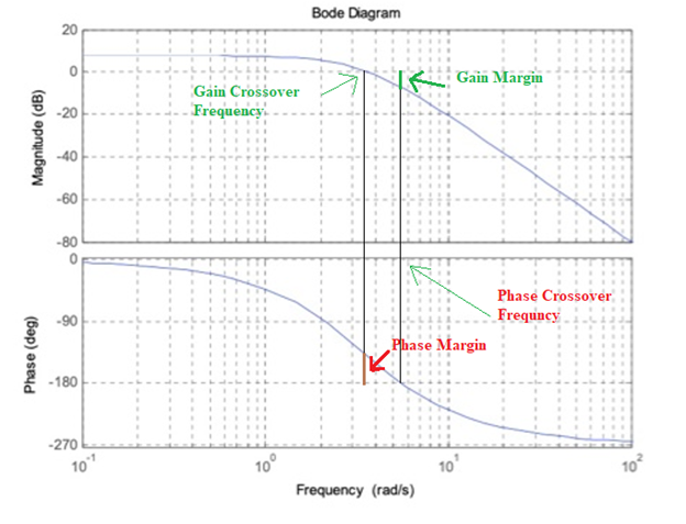
Bode Plot, Stability, Draw Bode Plot, Gain Margin & Phase Margin
Control signals in the frequency domain – Bode diagram a The amplitude ...
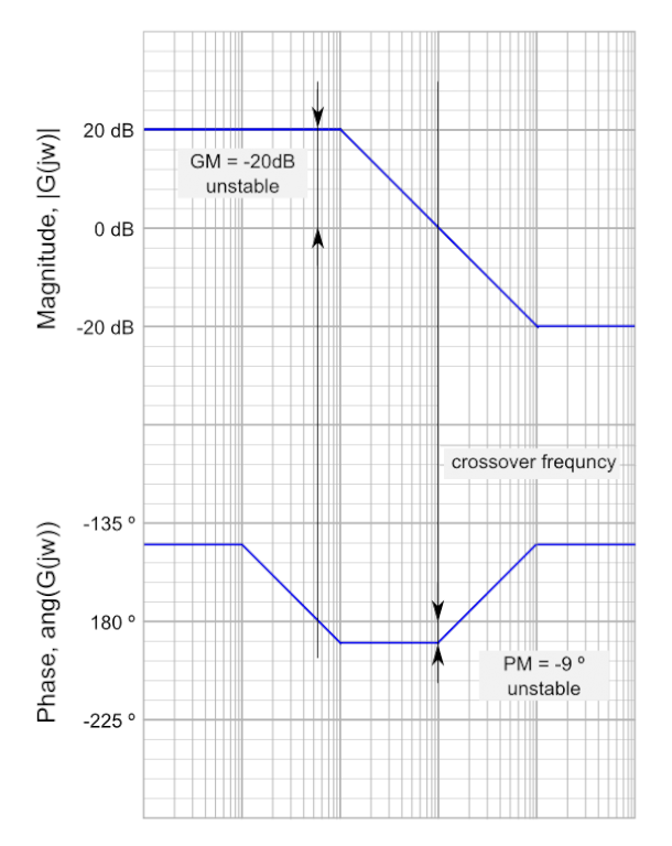
How to determine the stability of a CL-sys from BODE plots
PCB characteristics affect PDN performance - Engineering Technical - PCBway
Figure 4 from A 28-GHz Quadrature Fractional-N Frequency Synthesizer ...
Stability margin definitions. | Download Scientific Diagram
Simulated response (A) susceptance curve (B) susceptance slope ...
Figure 3 from A fully-scalable coplanar waveguide passive library for ...
Electrical test equipment | power station to plug | Megger
Bode diagram of the open‐loop transfer function for CC charging mode ...
Error amplifier limitations in high-performance regulator applications ...
PDX Series
Answered: 5. Consider the following Bode diagrams… | bartleby
shows the tuning capability of the LPF (a), HPF (b), BPF (c), and BSF ...
"Loss resonator" measurements. (a) Resonator footprints, average ...
Reflection phase of electromagnetic bandgap (EBG) structures for normal ...
Open loop plant bode plot | Download Scientific Diagram
BODE PLOT,PHASE MARGIN,CROSSOVER FREQUENCY AND STABILITY: BODE PLOT ...
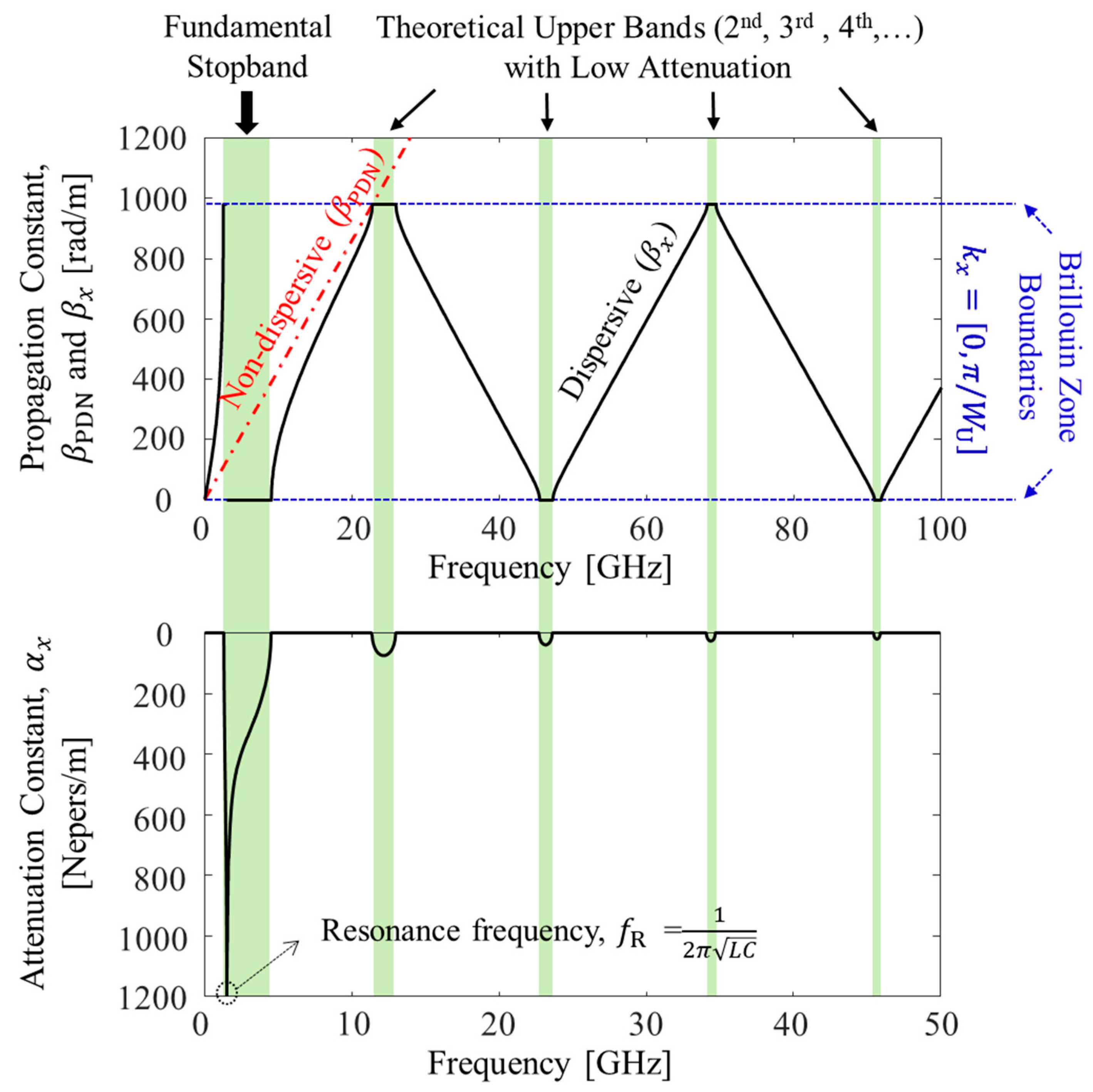
Micromachines | Free Full-Text | Design of Power/Ground Noise ...
Figure 2 from Design of multilayer spiral inductor resonator filter and ...
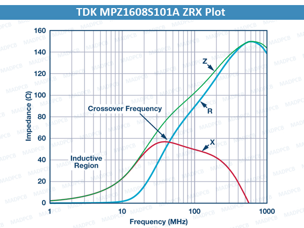
All about Ferrite Bead | MADPCB: PCB Layout, Fabrication and Assembly
Band‐pass filter frequency response | Download Scientific Diagram
Understanding Vented Enclosure Designs – FOH | Front of House Magazine
Ideal raised-cosine pulse shape (β = 0), duobinary and modified ...
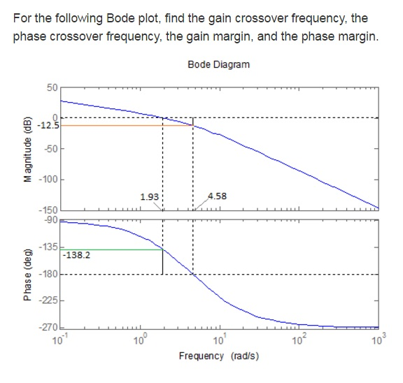
Solved For the following Bode plot, find the gain crossover | Chegg.com
The Asymptotic Bode Diagram - Erik Cheever
Natural frequency and modal damping of the disk–spindle system ...
9: Phase of (1 + 1.5G), desired phase of the multiplier and the ...
UCC28950 Phase Shifted Full Bridge Controller - YouSpice
Figure 2 from A circuit model of human whole blood in a microfluidic ...
S-Parameters vs. Frequency: Input Reflection Coefficient 0 Reverse ...
Figure 1 from Using Non-inear Chirp Waveform to Suppress Narrowband ...
Bode diagram of the output impedance of the VSG (a) Inherent impedance ...
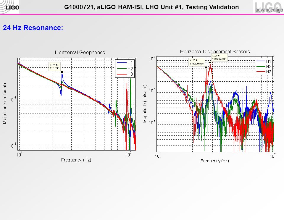
ALIGO HAM-ISI, LHO Unit #1, Testing Validation LIGO-G v1 July 23, 2010 ...
Phase-Margin-Bode-Plot
Bode-Gain-Plot
Low-Pass-Bode-Plot
Phase-Angle-Bode-Plot
Bode-Plot-Formula
Bode-Plot-Gain-Db20
Bode-Plot-Table
High-Pass-Filter-Bode-Plot
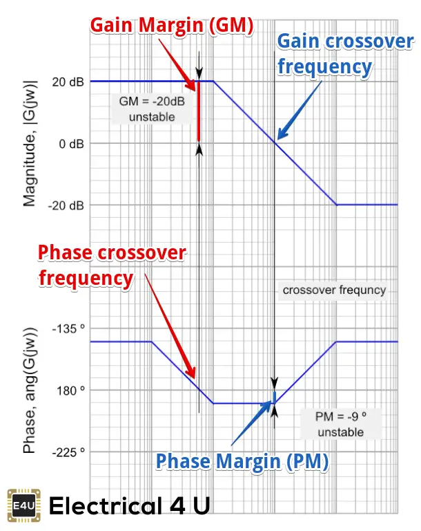
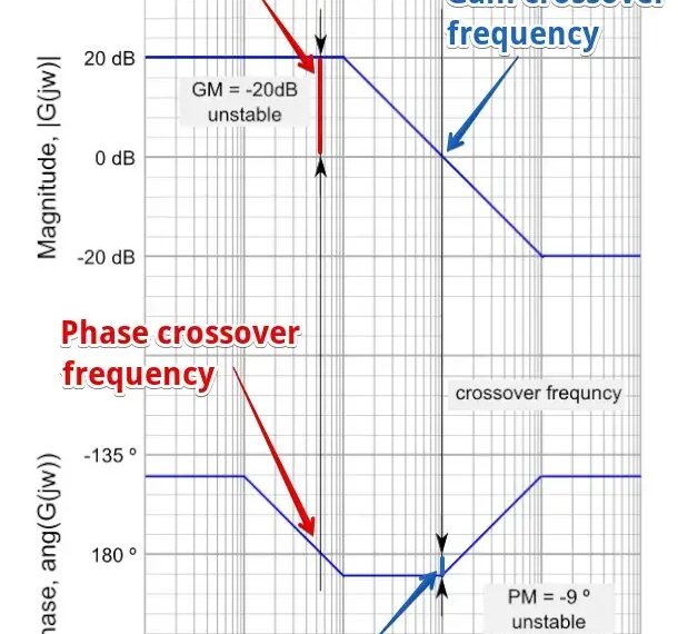
Unstable-Bode-Plot
Bode-Plot-Diagram
Nyquist-Plot
Bode-Plot-Examples
Unstable-System-Bode-Plot-Margin
First-Order-Bode-Plot
Gain-Crossover-Frequency-in-Bode-Plot
Simulink-Bode-Plot