Please enter url.
Login
Logout
Please enter url.
Reflection phase of electromagnetic bandgap (EBG) structures for normal ...
researchgate.net
source
Comments
Reflection phase of electromagnetic bandgap (EBG) structures for normal ...
Return loss characteristics obtained for the final layout. | Download ...
Spectrum characteristic analysis for the low flow-rate condition ...
Figure 1 from A study of coherent gain degradation due to node ...
Phase noise of the opto-mechanical oscillator (1) characterized with ...
Linear regulators vs. switchers for automotive applications - Embedded.com
Amplitude and phase of a steel with inhomogeneous thermal conductivity ...
Figure 15 from Design Techniques for Ultra-Low Voltage Analog Circuits ...
a) Side view schematic of a SrRuO 3 /LaYbO 3 /SrRuO 3 parallel plate ...
(PDF) An ultra wideband Wilkinson power divider
Figure 1 from 0.5 V Differential Difference Transconductance Amplifier ...
Reflection coefficient magnitude against frequency of the proposed ...
Archive - Sound article 9
Return loss characteristics obtained for the final layout. | Download ...
SBS-SCT based true-time delay line. For delays from 0.03 to 9.9 ns, the ...
Measured insertion and return loss for mixed frequency/bandwidth tuning ...
Figure 2 from A 18-40 GHz Full Connected Vivaldi Antenna Array ...
Magnitude (a) and phase (b) of the coupling coefficient for the active ...
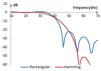
Hamming window | RecordingBlogs
The simulated reflection coefficients for different values of the ...
Reflection loss with variations of frequency. | Download Scientific Diagram
Mode displacements u x (in plane lying in sagittal plane) and ...
Sensors | Free Full-Text | Efficient Modulation and Processing Method ...
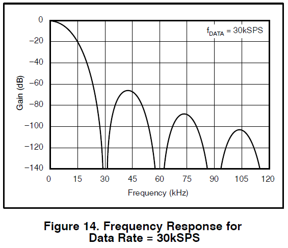
ADS1256 Clock in set to 250Hz - Data converters forum - Data converters ...
Propagation constants and loss tangent versus frequency for a UK coal ...
Figure 10 from Circularly-polarized 4-arm curl antenna for wireless ...
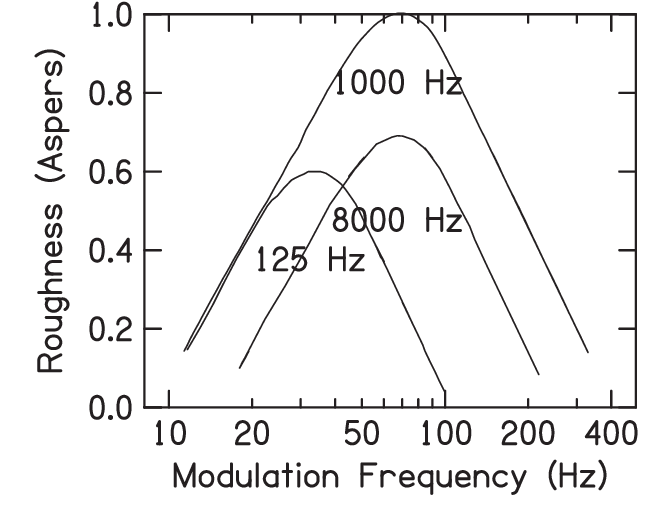
Figure 1 from The psychophysics of roughness applied to dysphonic voice ...
(a) The time-domain signals and (b) the frequency responses of wavelets ...
Figure 1 from A low power and high conversion gain 94 GHz up-conversion ...
Figure 4 from Design of a Ka-Band LNA Based on 150 nm GaN-on-Si ...
Bode diagram considering parametric variations: from 10 to 150% of ...
PRC’s of different antenna models according to the simulated antenna ...
Figure 1 from A 9-to-42-GHz High-Gain Low-Noise Amplifier Using Coupled ...
Figure 3 from Design of an S-Band Chireix Outphasing Power Amplifier ...
Source time function with different duration (a). Fourier spectrum (b ...