Please enter url.
Login
Logout
Please enter url.
9: Phase of (1 + 1.5G), desired phase of the multiplier and the ...
researchgate.net
source
Comments
Figure 4 from Complex conjugate pole analysis for bandwidth extension ...
Impulse response invariant discretization of BICO (Bode's Ideal Cut-Off ...
Verify Standalone CTLE in Architectural, Behavioral, and Circuit ...
4 Bode plot of transfer function G 1 (s) 5.3.3 Some other plots You can ...
Joint delay Doppler pdf p ( t ; τ , f d ) | Download Scientific Diagram
Comparison of the True Unstable System and Estimated Unstable Model at ...
Figure 10 from Numerator-Denominator Model Based H∞ Robust Control for ...
Bode plot based on comparing GSs with K∞ and the transfer function. (a ...
Energies | Free Full-Text | Rigid-Flexible Modal Analysis of the ...
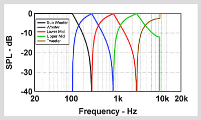
Constant directivity loudspeaker designs
Non-Linearity Impacts on Switched-Capacitor Filter Design - Planet Analog
Phase compensator G c1 (s) (left), compensated G 2 (s) (right ...
Frequency response of a mass-spring-damper system with hysteretic ...
Sub‐synchronous oscillation mechanism and its suppression in MMC‐based ...
what is minimum phase and how does it apply to passive components ...
CTM Example: Frequency Response Design Method For Bus Suspension System
1 { Optimal vs G a (p) approximated transfer function. | Download ...
The Role of Servo Drives in a Motion Control System - Technical Articles
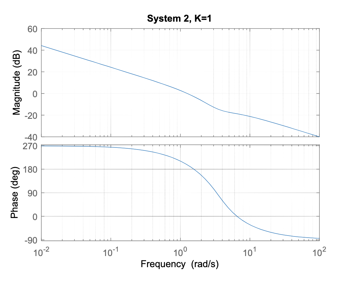
Solved 2. For the following system, use a Bode plot for K =1 | Chegg.com
Bode plot for changing length for hollow tapered shaft rotor with ...
oscillation in a low bandwidth(300Hz) trans impedance circuit ...
Bode diagram of PSFB transfer function H 2 , with parameters from Table ...
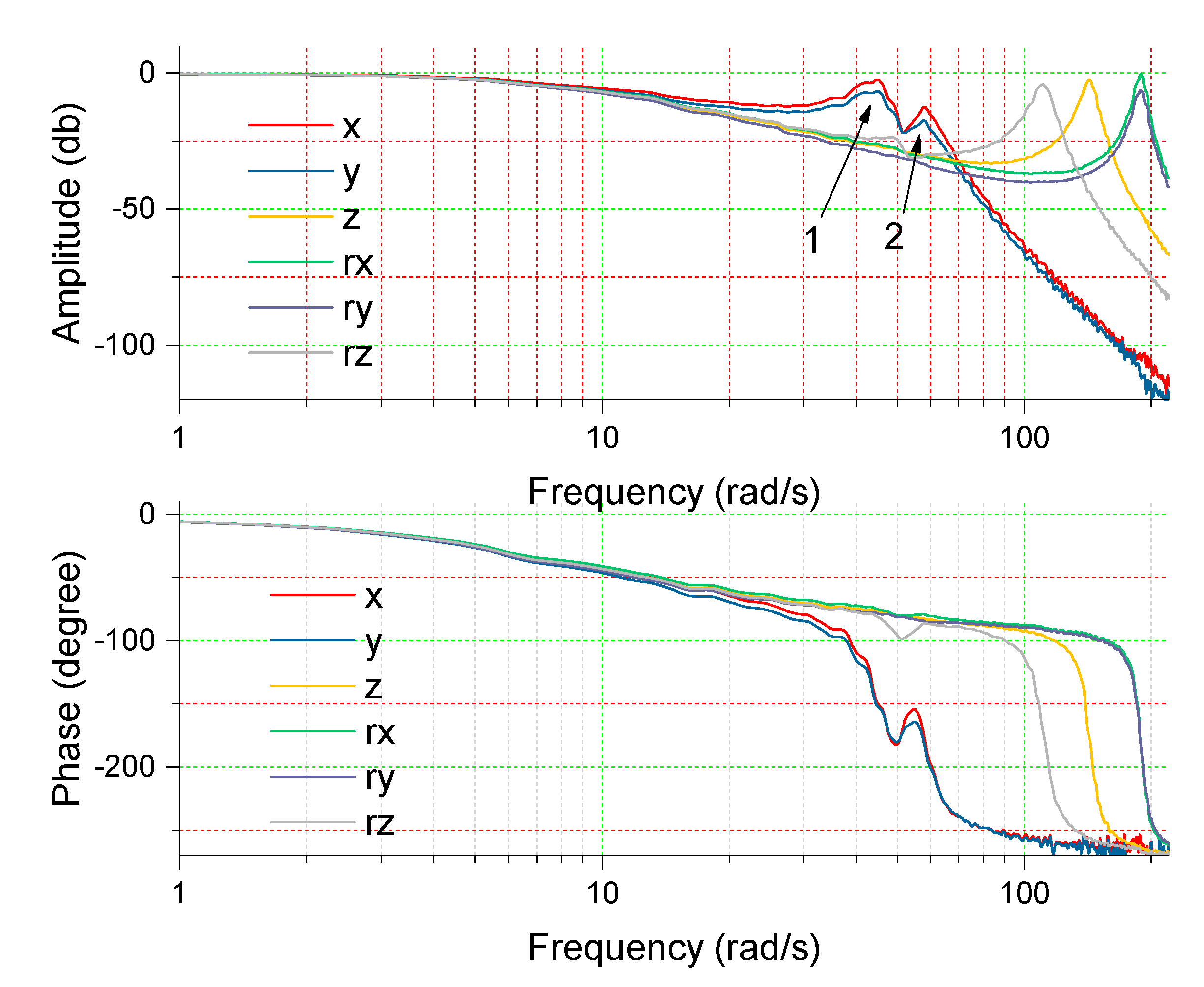
voltage to force transfer function for the cabinet transducers ...
Dipole on axis
Bode diagram of the shaker system with the acceleration response (solid ...
A review on control methodologies of disturbance rejections in optical ...
Bode diagram of identified modeî P(z) of the plant P(z). A 48thorder ...
Frequency responses of inverter output impedance d component and grid ...
Bode diagram of current close‐loop | Download Scientific Diagram
CL active power; WT active power. | Download Scientific Diagram
Mode superposition of the y DOF. | Download Scientific Diagram
Figure 1 from Analysis and design of HBT Cherry-Hooper amplifiers with ...
Figure 1 from Design of Output LCL Filter for 15-level Cascade Inverter ...
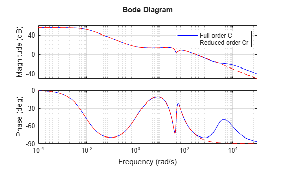
Simultaneous Stabilization Using Robust Control - MATLAB & Simulink Example
Impact of the proportional gain of the ac voltage controller on the MMC ...