Please enter url.
Login
Logout
Please enter url.
How to plot bode plot multisim - intlvsa
intlvsa.weebly.com
source
Comments
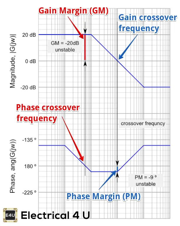
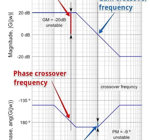
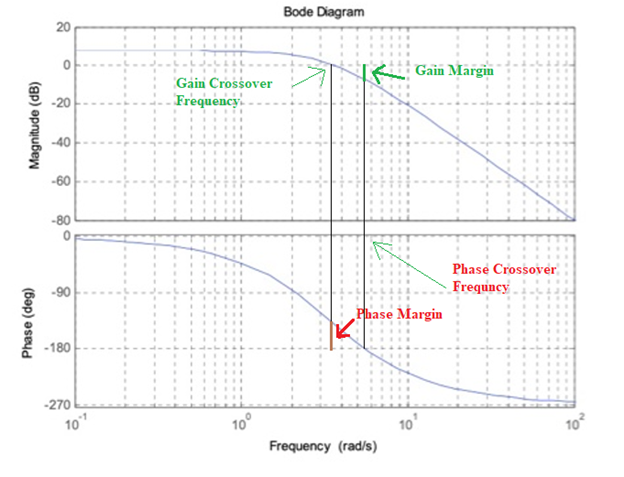
Bode Plot, Gain Margin and Phase Margin (Plus Diagram) | Electrical4U ...
Bode Plot, Stability, Draw Bode Plot, Gain Margin & Phase Margin
Control signals in the frequency domain – Bode diagram a The amplitude ...
Some features of the Bode plot of a complex lead compensator. The Bode ...
How to determine the stability of a CL-sys from BODE plots
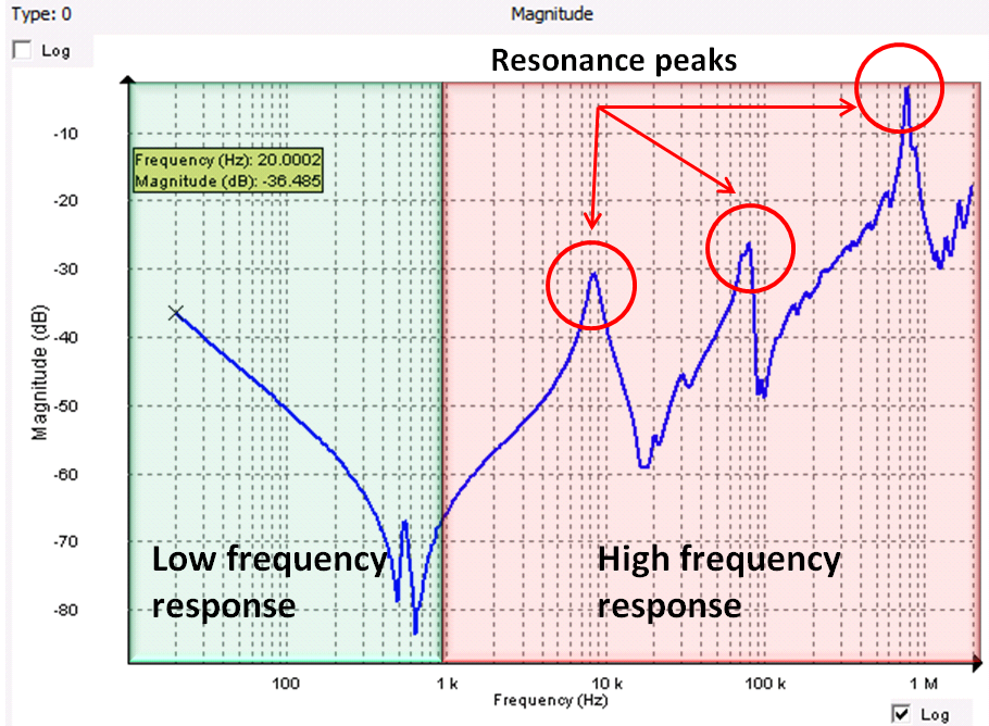
PCB characteristics affect PDN performance - Engineering Technical - PCBway
Figure 4 from A 28-GHz Quadrature Fractional-N Frequency Synthesizer ...
Stability margin definitions. | Download Scientific Diagram
Simulated response (A) susceptance curve (B) susceptance slope ...
Figure 3 from A fully-scalable coplanar waveguide passive library for ...
Electrical test equipment | power station to plug | Megger
Bode diagram of the open‐loop transfer function for CC charging mode ...
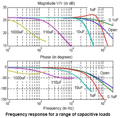
Error amplifier limitations in high-performance regulator applications ...
PDX Series
Answered: 5. Consider the following Bode diagrams… | bartleby
shows the tuning capability of the LPF (a), HPF (b), BPF (c), and BSF ...
Frequency Response for Control Systems - National Instruments
"Loss resonator" measurements. (a) Resonator footprints, average ...
Reflection phase of electromagnetic bandgap (EBG) structures for normal ...
Open loop plant bode plot | Download Scientific Diagram
Bode Plots for Second-Order Lowpass Filters with Corner Resonance
ECE 3110 - Lecture 15c: Using Bode Plots to Find Phase Margin - YouTube
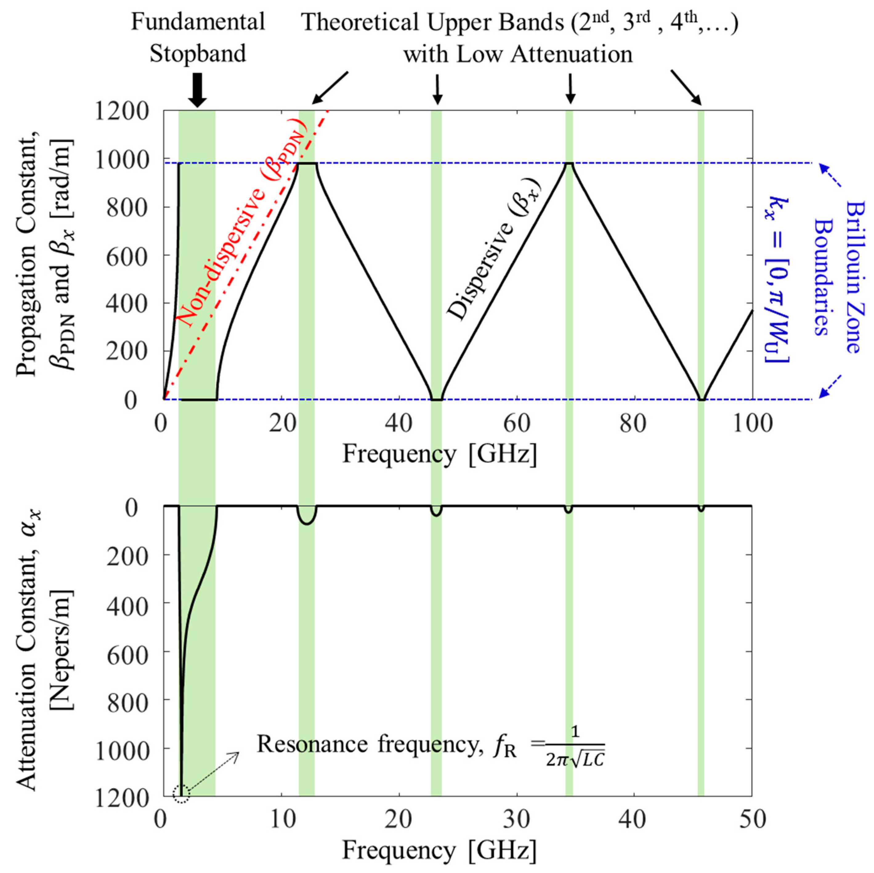
Micromachines | Free Full-Text | Design of Power/Ground Noise ...
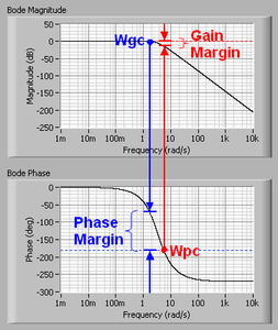
Bode Plot, Phase Margin, Crossover Frequency, and Stability - EEWeb
Figure 2 from Design of multilayer spiral inductor resonator filter and ...
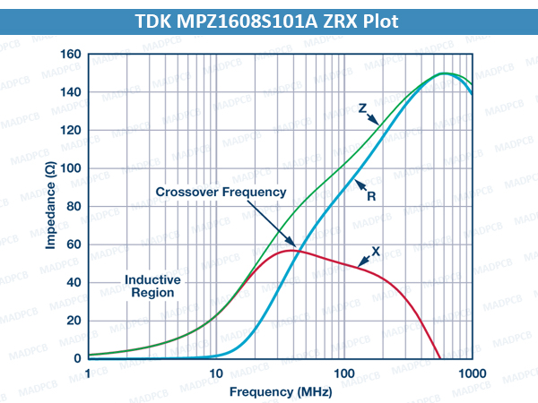
All about Ferrite Bead | MADPCB: PCB Layout, Fabrication and Assembly
Band‐pass filter frequency response | Download Scientific Diagram
Understanding Vented Enclosure Designs – FOH | Front of House Magazine
Ideal raised-cosine pulse shape (β = 0), duobinary and modified ...
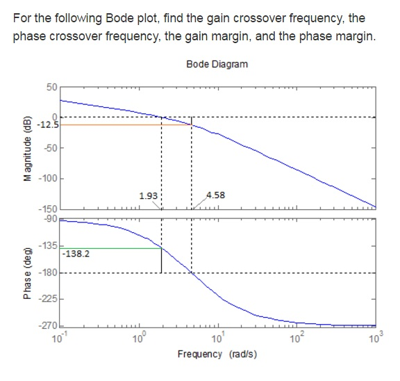
Solved For the following Bode plot, find the gain crossover | Chegg.com
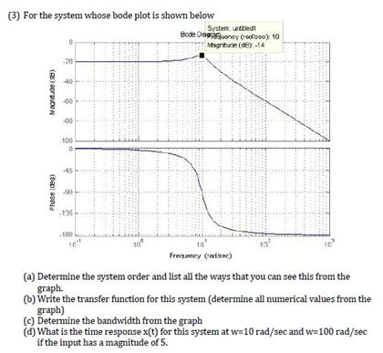
For the system whose bode plot is shown below | Chegg.com
The Asymptotic Bode Diagram - Erik Cheever
FAQ: How are crossover frequencies used in servo motor tuning?
Natural frequency and modal damping of the disk–spindle system ...
9: Phase of (1 + 1.5G), desired phase of the multiplier and the ...
Phase-Margin-Bode-Plot
Bode-Gain-Plot
Low-Pass-Bode-Plot
Phase-Angle-Bode-Plot
Bode-Plot-Gain-Db20
Bode-Plot-Table
Bode-Plot-Formula
High-Pass-Filter-Bode-Plot
Unstable-Bode-Plot
Bode-Plot-Diagram
Nyquist-Plot
Gain-Crossover-Frequency-in-Bode-Plot
Simulink-Bode-Plot
First-Order-Bode-Plot
Bode-Plot-Examples
Bode-Plot-Gain-Calculate