Please enter url.
Login
Logout
Please enter url.
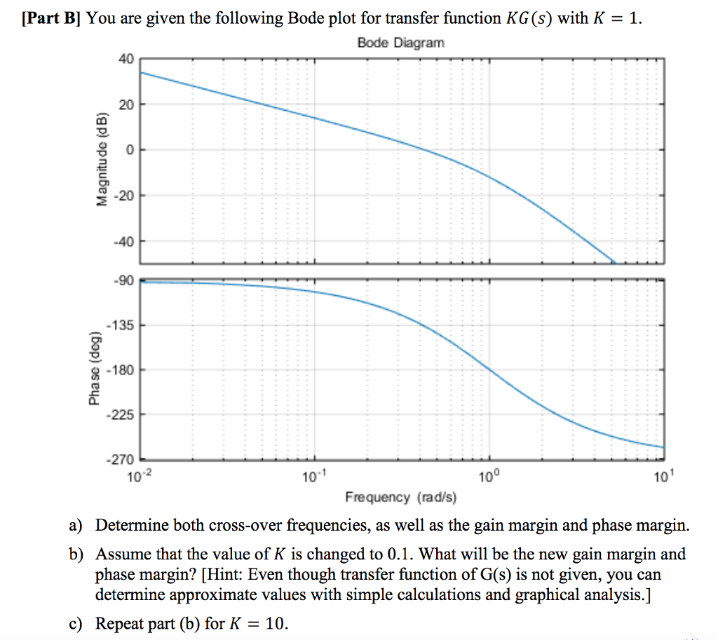
Solved Part B! You are given the following Bode plot for | Chegg.com
chegg.com
source
Comments
Bode plots of the fractional-order low-pass filter (F (s)) for ...
The Amplitude-Frequency characteristics before and after Expansion ...
Bode plots for MS-TMM and classical method. | Download Scientific Diagram
SISO-OFDM simulation of COS companding method with LMMSE pre-equalizer ...
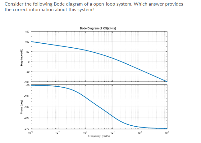
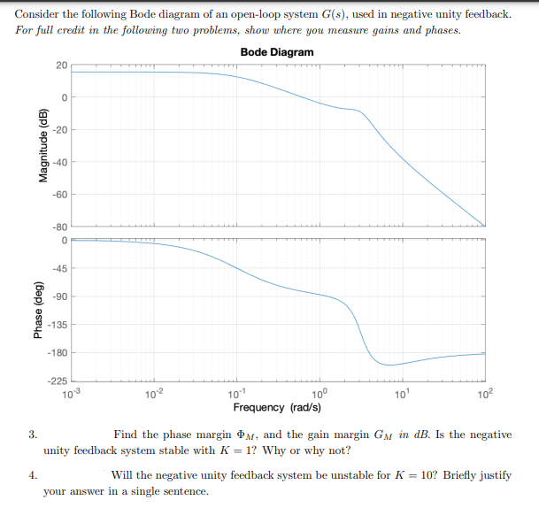
Solved Consider the following Bode diagram of a open-loop | Chegg.com
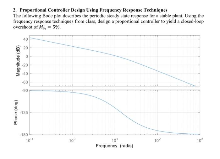
2. Proportional Controller Design Using Frequency | Chegg.com
6.2: Measures of Performance - Engineering LibreTexts
14: Beam waist radius and estimated truncation losses at the ...
Sensitivity function of the closed-loop error with respect to output ...
Solved Consider the system shown in state-space form below. | Chegg.com
Margin to coolant boiling gained during each transient as a function of ...
The dynamics of an uncompensated electro-hydraulic actuator and its ...
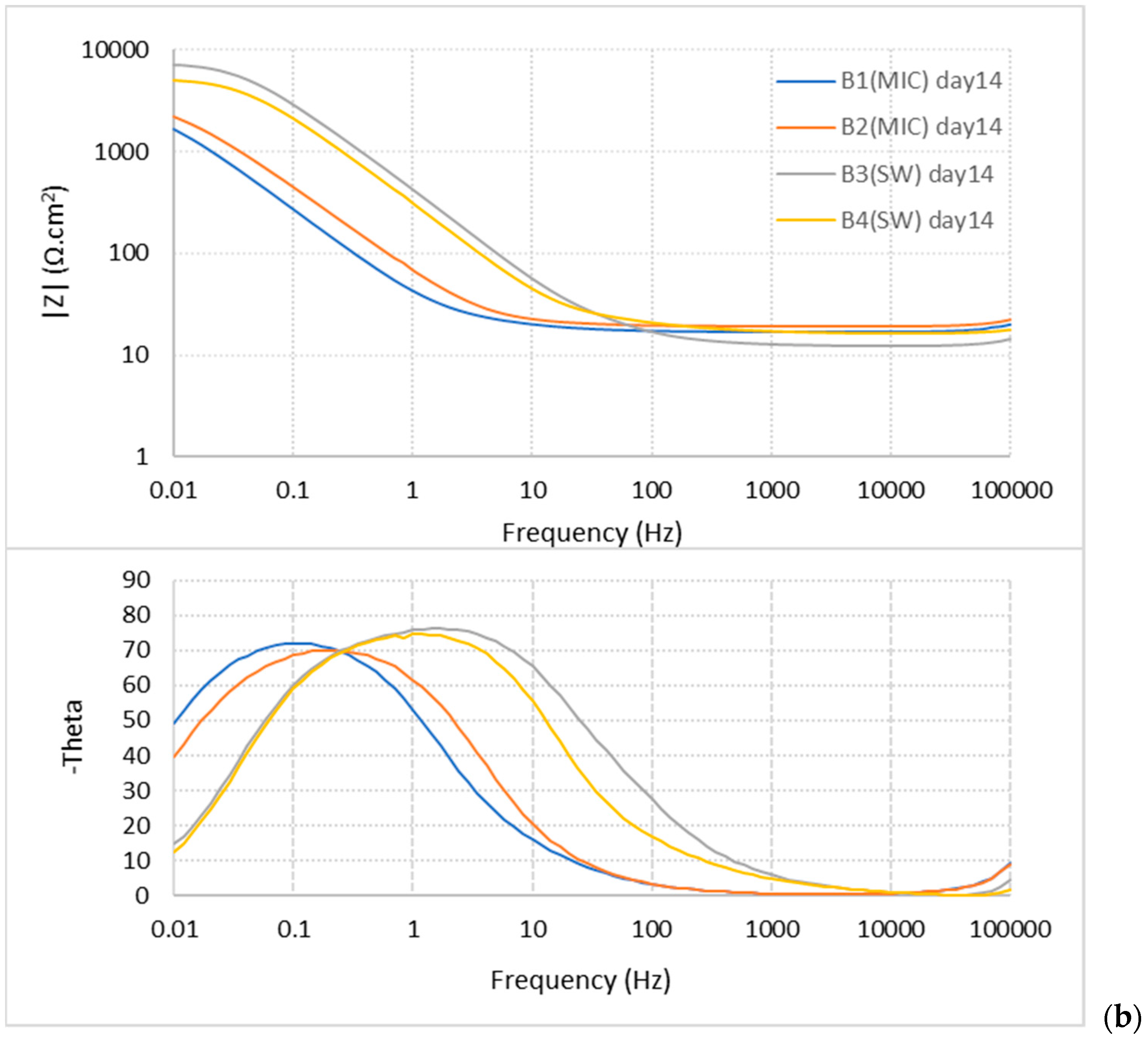
CMD | Free Full-Text | Localized Corrosion of Mooring Chain Steel in ...
jees :: Journal of Electromagnetic Engineering and Science
Solved Determine the gain and phase margins (GM, PM) of the | Chegg.com
Wideband and high‐gain circularly polarised microstrip antenna design ...
Performance of the 10 mm-long capacitor-impregnated microstrip: (a ...
Energies | Free Full-Text | Phase-Locked Loop Research of Grid ...
(a) Geometry of the unit cells of the AMC structures and (b) simulated ...
Analysis of voltage fluctuation impact on induction motors by an ...
Processes | Free Full-Text | Development of an Online Monitoring Device ...
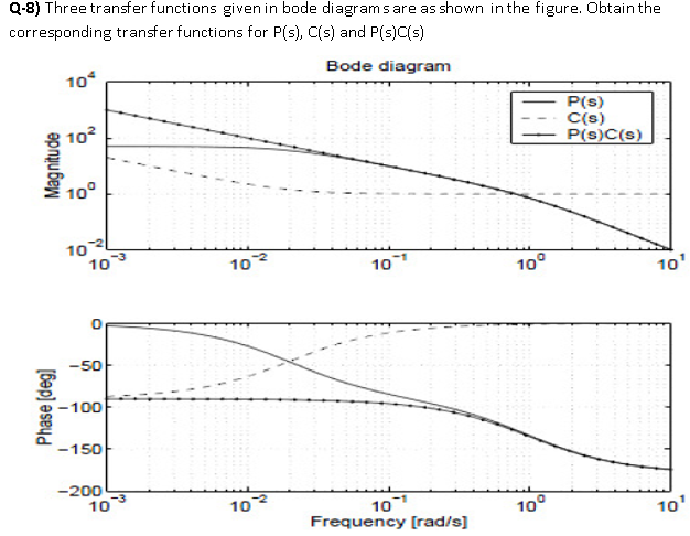
Solved Q-8) Three transfer functions given in bode diagrams | Chegg.com
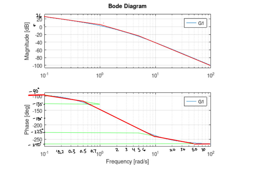
Solved Given the Bode plot, determine the transfer | Chegg.com
Solved Consider a unity feedback closed-loop system. The | Chegg.com
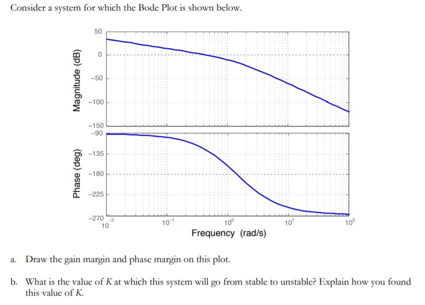
Solved Consider a system for which the Bode Plot is shown | Chegg.com
2. For each of the Bode plots shown on the next two | Chegg.com
5.1. Frequency Response Design of a Lead Compensator — EGLM03 Modern ...
Parker Servo Valve approximated dynamics. | Download Scientific Diagram
Solved Plotted above are the Magnitude and Phase Responses | Chegg.com
Sensors | Free Full-Text | FPGA-Based Degradation and Reliability ...
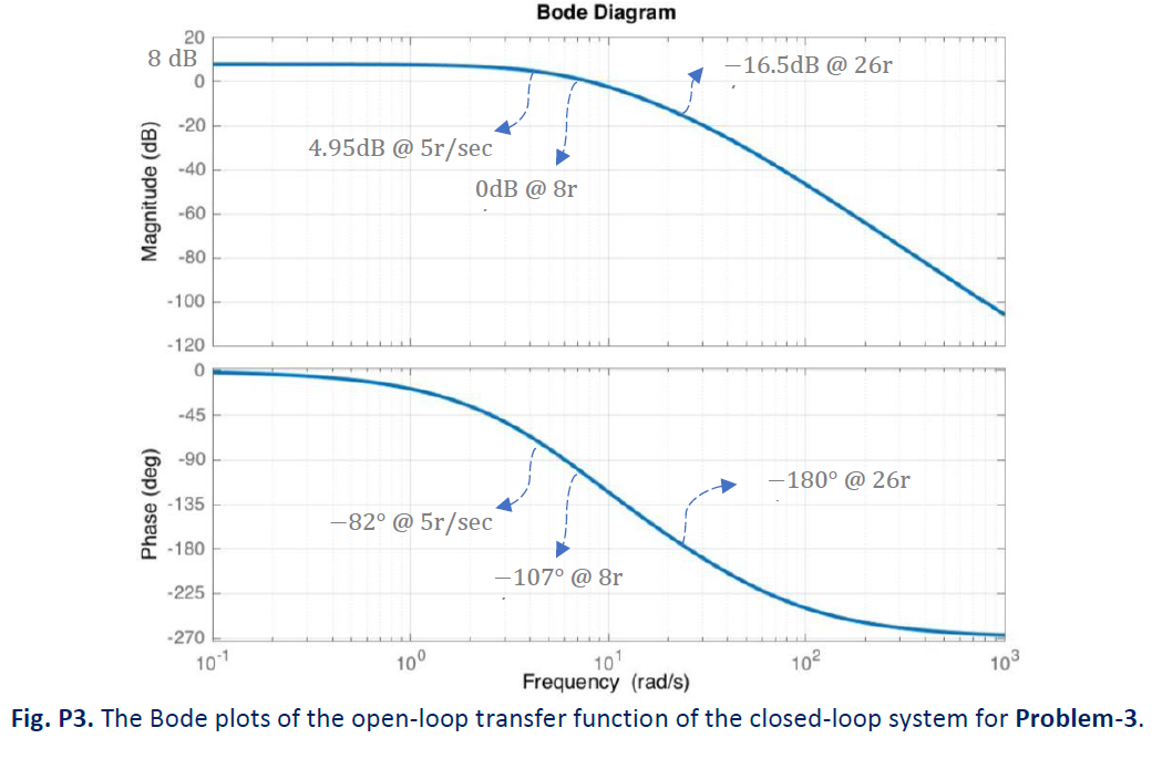
Solved Problem 3. Considering the Bode magnitude and phase | Chegg.com
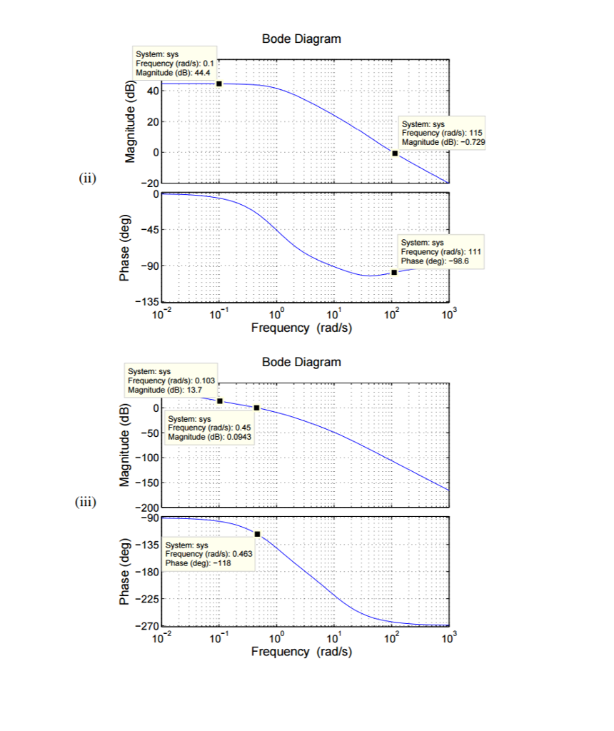
Solved (ii) Bode Diagram System: sys Frequency (rads): 0.1 T | Chegg.com
Energies | Free Full-Text | Small-Signal Modeling of Phase-Shifted Full ...
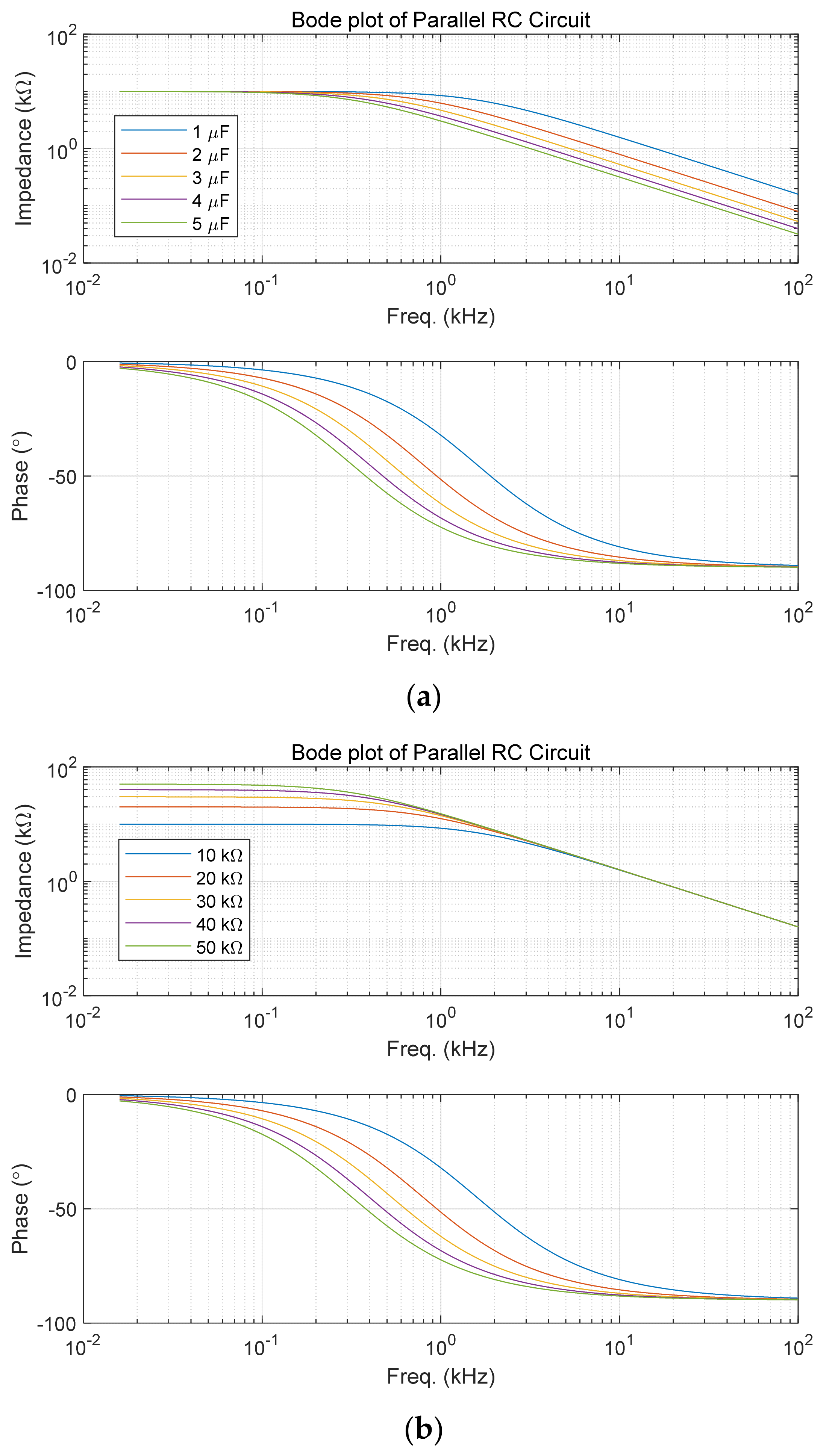
(a) RLC circuit configuration and (b) its impedance Z behavior. Great ...
A comparison of gain diagrams of í µí°» 5 í µí± í µí± (í µí± ) and of ...