Please enter url.
Login
Logout
Please enter url.
The dynamics of an uncompensated electro-hydraulic actuator and its ...
researchgate.net
source
Comments
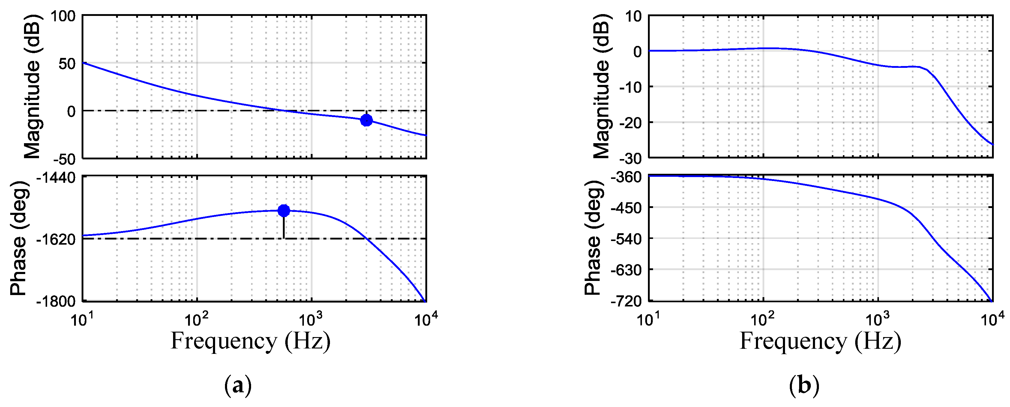
Parker Servo Valve approximated dynamics. | Download Scientific Diagram
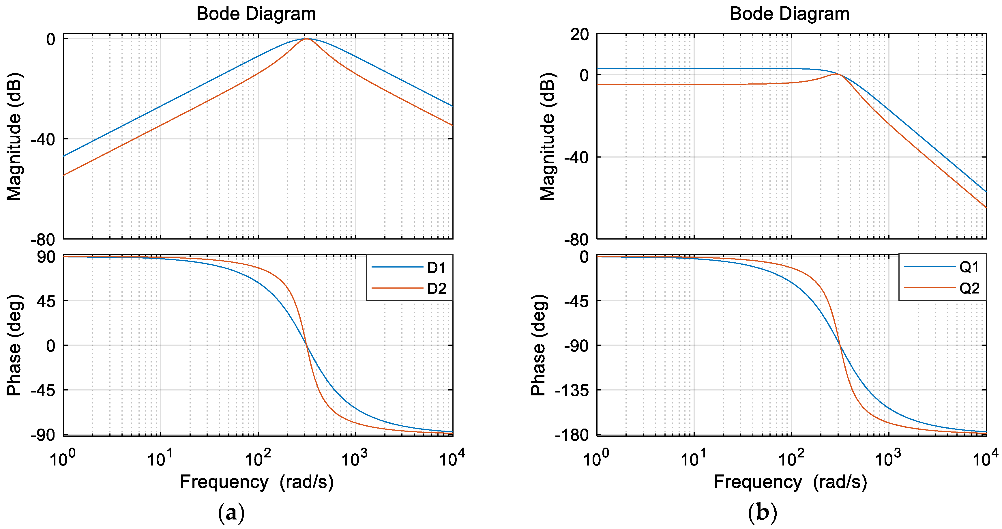
Energies | Free Full-Text | Modeling and Parameter Design of Voltage ...
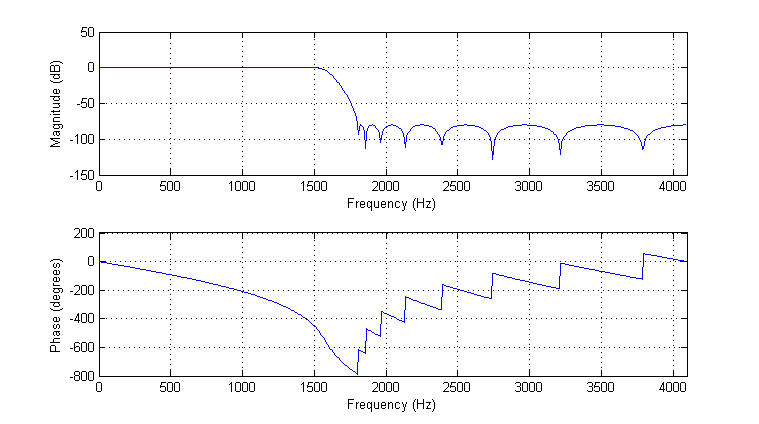
MSP DSP Library: Filter Coefficient Generation
Figure 13 from Modeling and controller design of a bidirectional ...
The Bode diagram for n = 2 , N = 100 , and N = 50 . | Download ...
Electronics | Free Full-Text | An 8-Gbps, Low-Jitter, Four-Channel ...
(PDF) Clamp-Force Estimation for a Brake-by-Wire System: A Sensor ...
SISO-OFDM simulation of COS companding method with LMMSE pre-equalizer ...
Frequency responses of x- and y-axes, respectively. | Download ...
Amplitude-frequency characteristic curves. | Download Scientific Diagram
Sound Propagation in a Duct with Wall Corrugations Having Square-Wave ...
Typical measured impedance spectra (magnitude and phase) for monopolar ...
Conventional IIR notch filter frequency response: (a) The attenuation ...
(PDF) Howling Detection and Suppression Based on Segmented Notch Filtering
Energies | Free Full-Text | Phase-Locked Loop Research of Grid ...
Solved Problem 7. Among the transfer functions listed below, | Chegg.com
Phase frequency characteristic curves. | Download Scientific Diagram
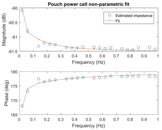
Batteries | Free Full-Text | Accelerated Internal Resistance ...
CTM Example: Frequency Design Method for DC Motor Speed Control
Bode diagram of output impedance ( Z v = 0 ). | Download Scientific Diagram
Sensors | Free Full-Text | Resonance Suppression of Servo System Based ...
Theoretical and experimental frequency response of the CL converter ...
Path loss vs. distance between two coils for two different operating ...
Design of a dual-tone controller for Lissajous-based scanning of fast ...
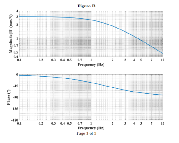
Solved 4 Figures A and B on the next page each show the | Chegg.com
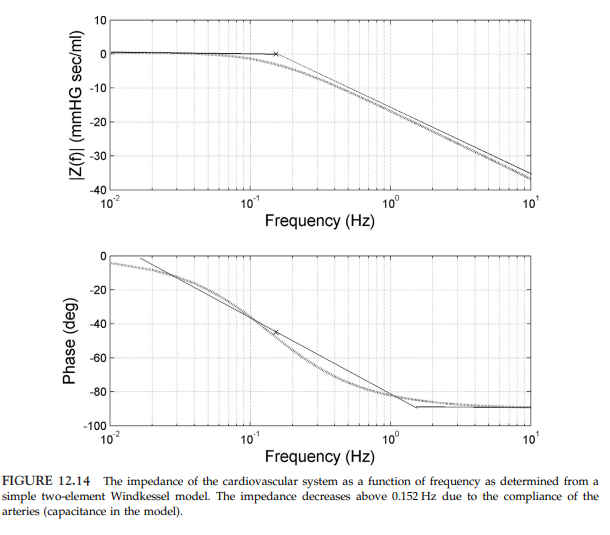
Solved FIGURE 12.14 The impedance of the cardiovascular | Chegg.com
Considering the system shown in the Figure 6: R(S) | Chegg.com
Characterisation of a Standard Fan Test Facility to Accommodate ...
41. Flight path response to pilot stick input (coaxial-pusher and ...
Closed loop output impedance comparison. | Download Scientific Diagram
Figure 1 from Analysis and Design Considerations of Integrated 3-Level ...
control system - Interpreting bode plot of type 3 compensation network ...
(a) Geometry of the unit cells of the AMC structures and (b) simulated ...
Average error of estimated angles for different pitch frequencies ...
Vertical vehicle body acceleration PSD plots at four corners with high ...