Please enter url.
Login
Logout
Please enter url.
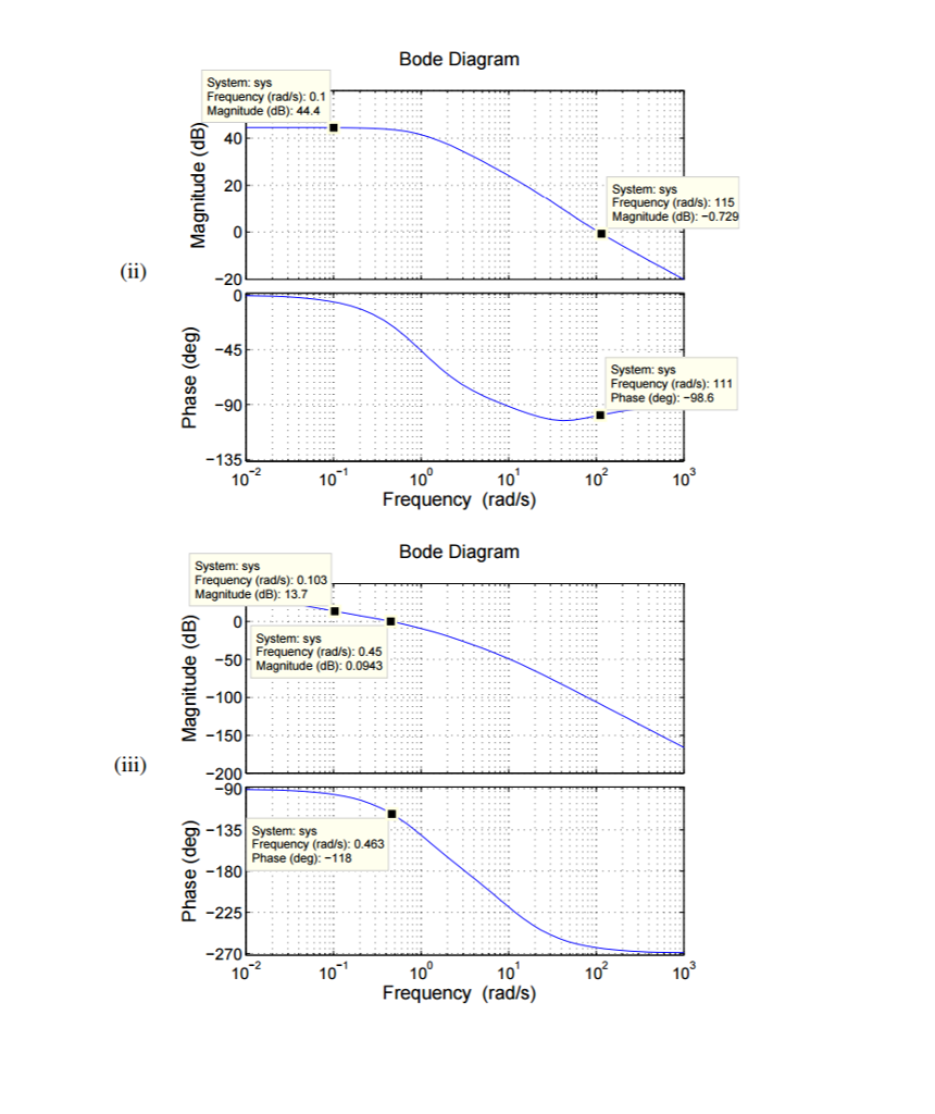
Solved (ii) Bode Diagram System: sys Frequency (rads): 0.1 T | Chegg.com
chegg.com
source
Comments
41. Flight path response to pilot stick input (coaxial-pusher and ...
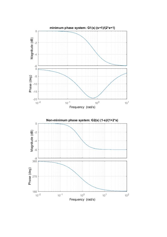
A comparison of gain diagrams of í µí°» 5 í µí± í µí± (í µí± ) and of ...
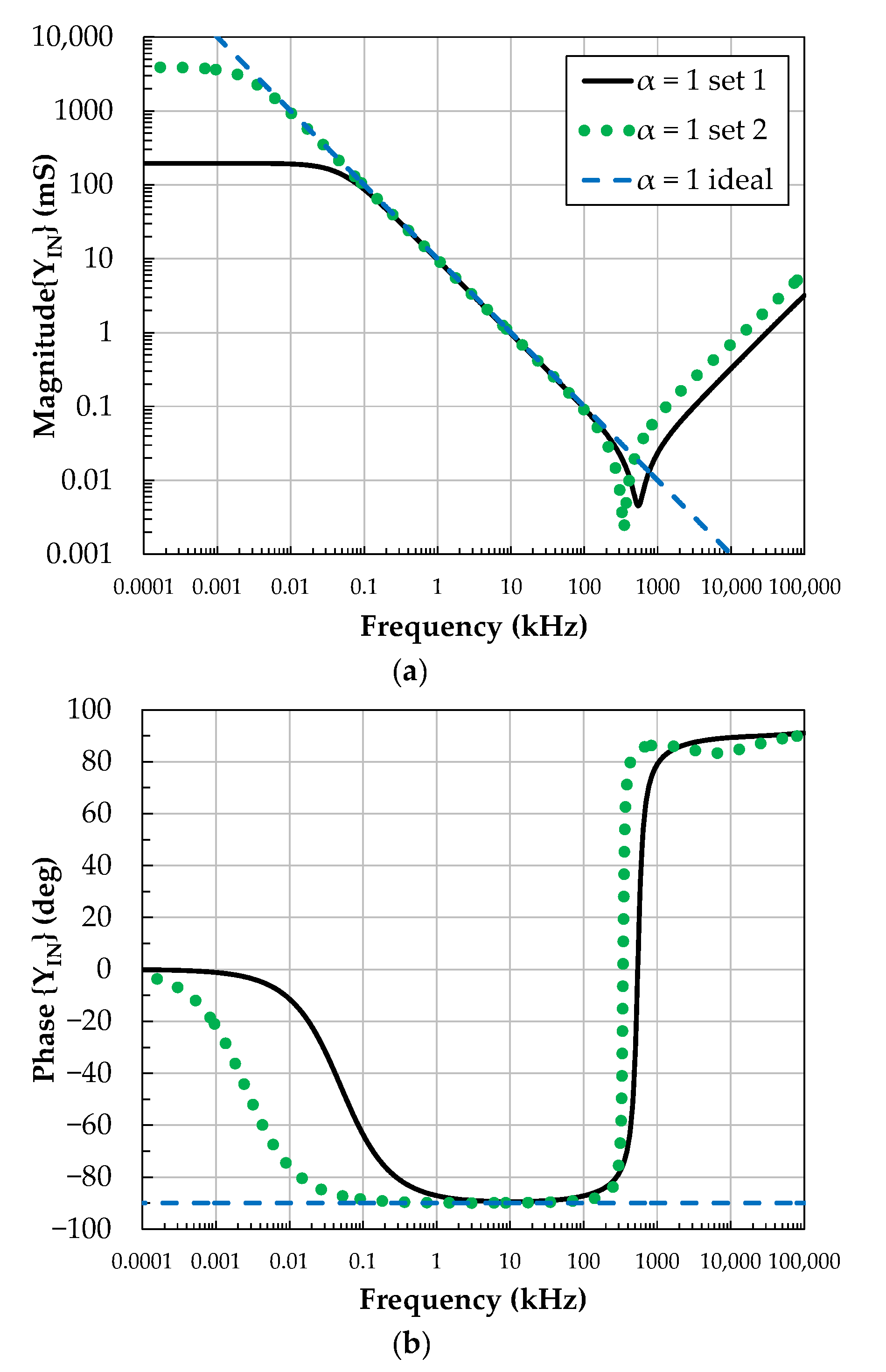
Applied Sciences | Free Full-Text | Optimized Design of OTA-Based ...
Sparkos Labs, Inc. Audio op amp discrete in an API package
Frequency response of our BPF. | Download Scientific Diagram
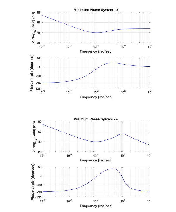
control system - Interpreting bode plot of type 3 compensation network ...
Magnitude characteristics of the LPF, HPF, BPF, BSF with process corner ...
Solved Please select the correct Bode plot, that corresponds | Chegg.com
Solved 1. a) Consider a buck converter operating at a | Chegg.com
Modern Control Engineering - 9780136156734 - Exercise 3 | Quizlet
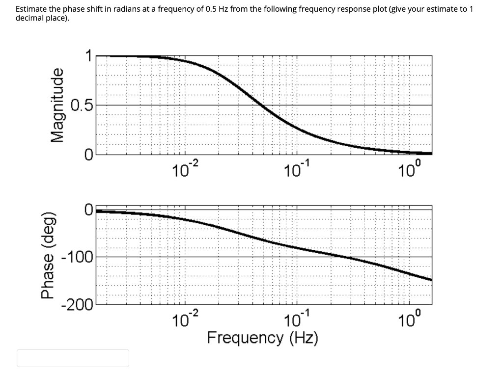
Solved Estimate the phase shift in radians at a frequency of | Chegg.com
DC terminal impedance Bode plot for the rectifier terminal. (a) Output ...
Figure 3 from Overview of wideband Butler matrix in microstrip-slot ...
The Chebyshev digital bandpass filter of 8th order. | Download ...
Loop impedances between the phase A and the sheath of the sector-shaped ...
Transfer function T r (s) from reference position x e,d to absolute ...
9. Bode plot of a) frequency-control and b) phase-control loop gains ...
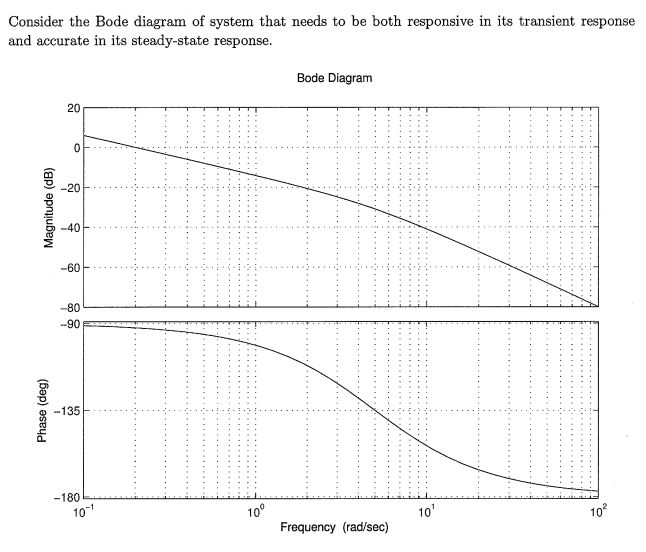
Solved Consider the Bode diagram of system that needs to be | Chegg.com
CTM Example: Frequency Design Method for DC Motor Position Control
P-Vr characteristics of a generator in a large system for a very wide ...
Solved 2. The block diagram shown in Figure 1(a) represents | Chegg.com
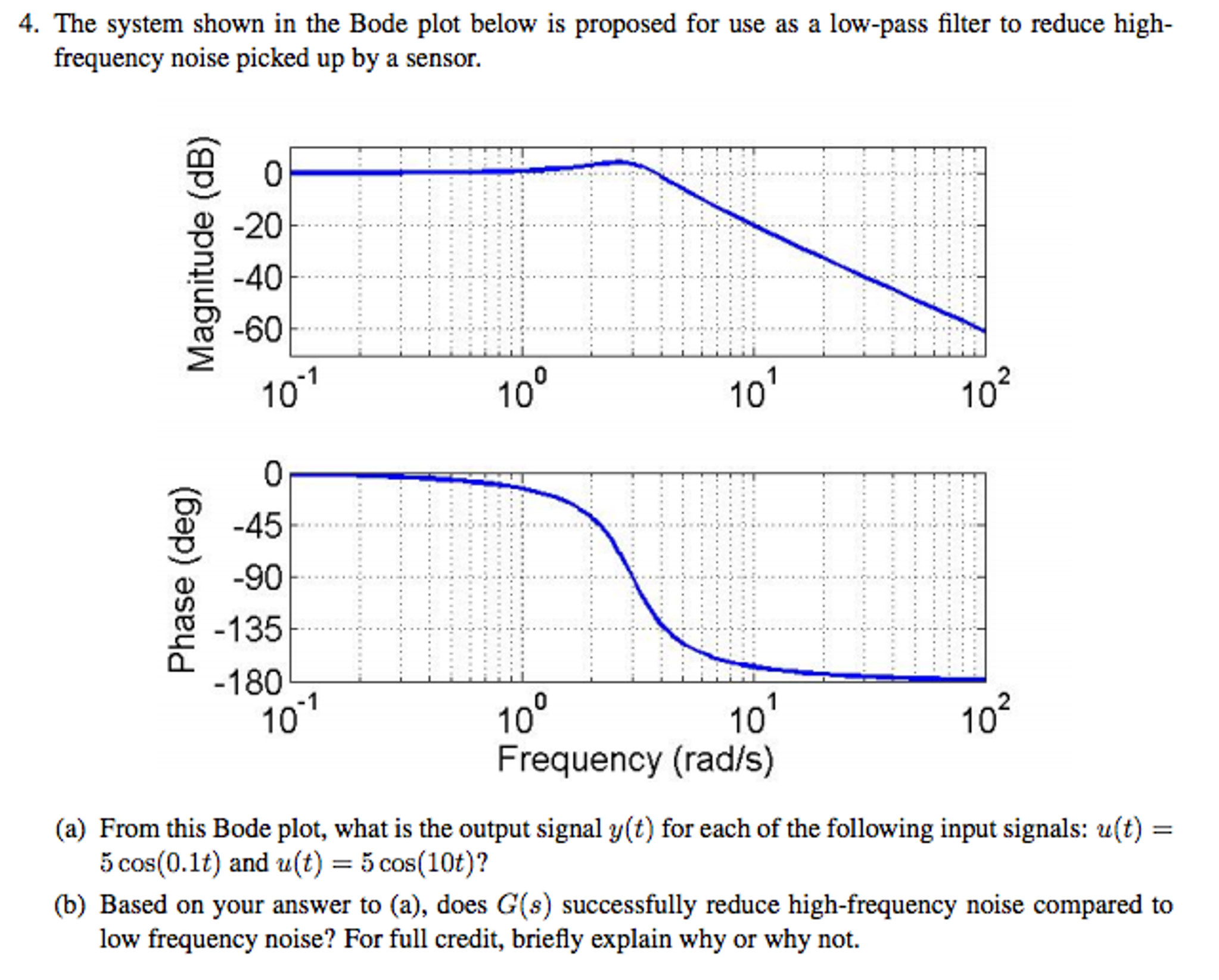
Solved The system shown in the Bode plot below is proposed | Chegg.com
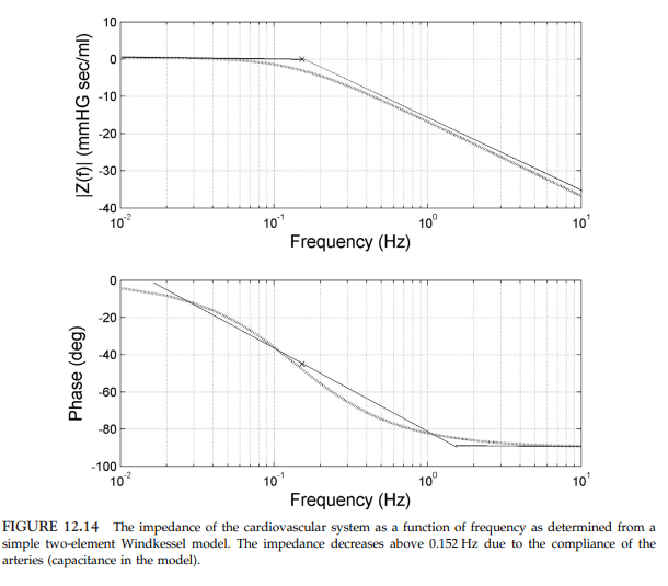
Solved FIGURE 12.14 The impedance of the cardiovascular | Chegg.com
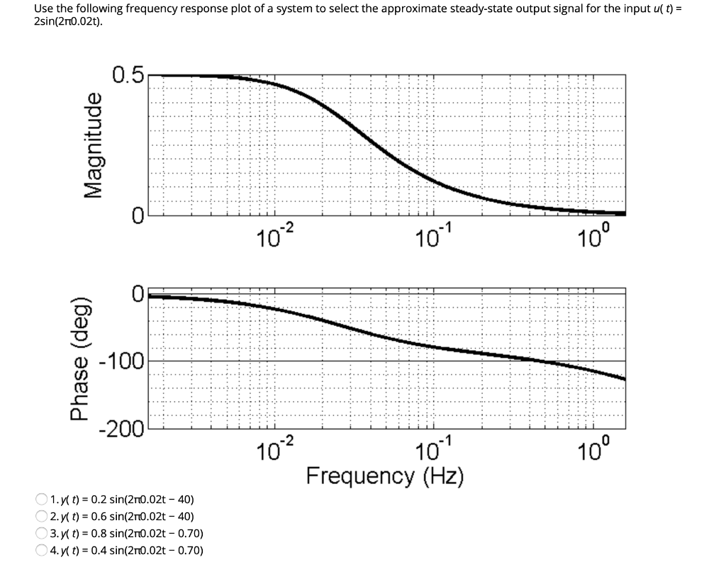
Solved Use the following frequency response plot of a system | Chegg.com
15 Bode diagrams of the PID and Youla controllers for the fourth order ...
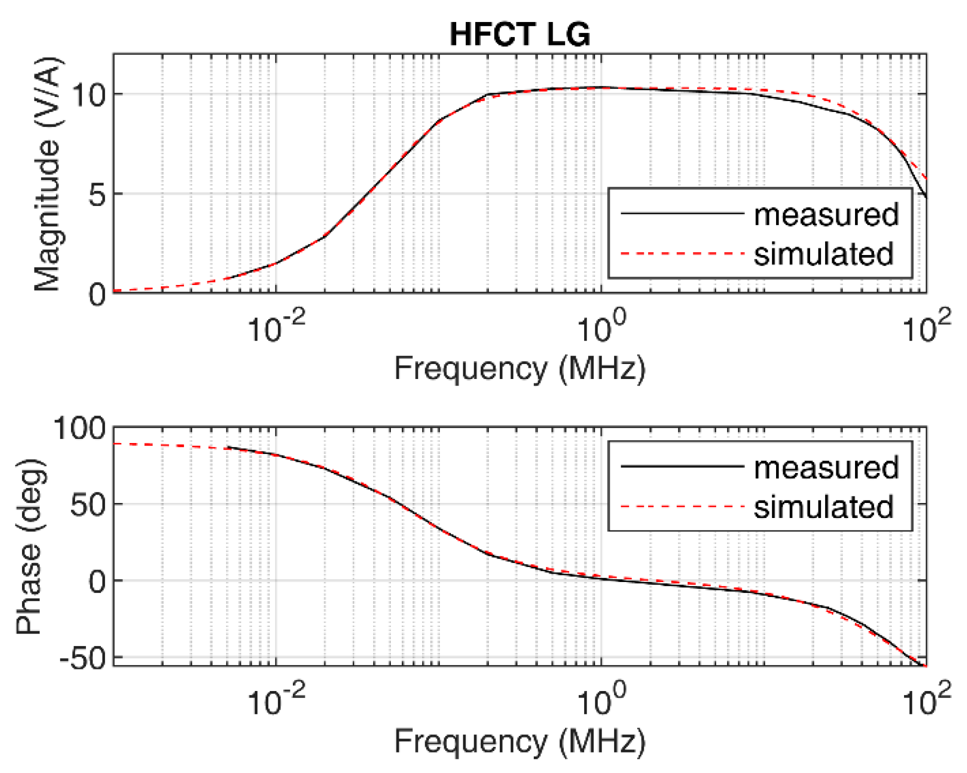
Sensors | Free Full-Text | Principles of Charge Estimation Methods ...
Bode plot of the proposed torque regulator with varying id values. 1 ...
9: Bode plot in axis x. | Download Scientific Diagram
Figure 10 from Design of Modified Jacobi Microstrip Lowpass Filter for ...
EE 212 - Frequency Response Example 3
Energies | Free Full-Text | Improved Reactive Current Detection Method ...
Electronics | Free Full-Text | Effectiveness Assessment of a ...
Frequency Design Method for DC Motor Speed Control
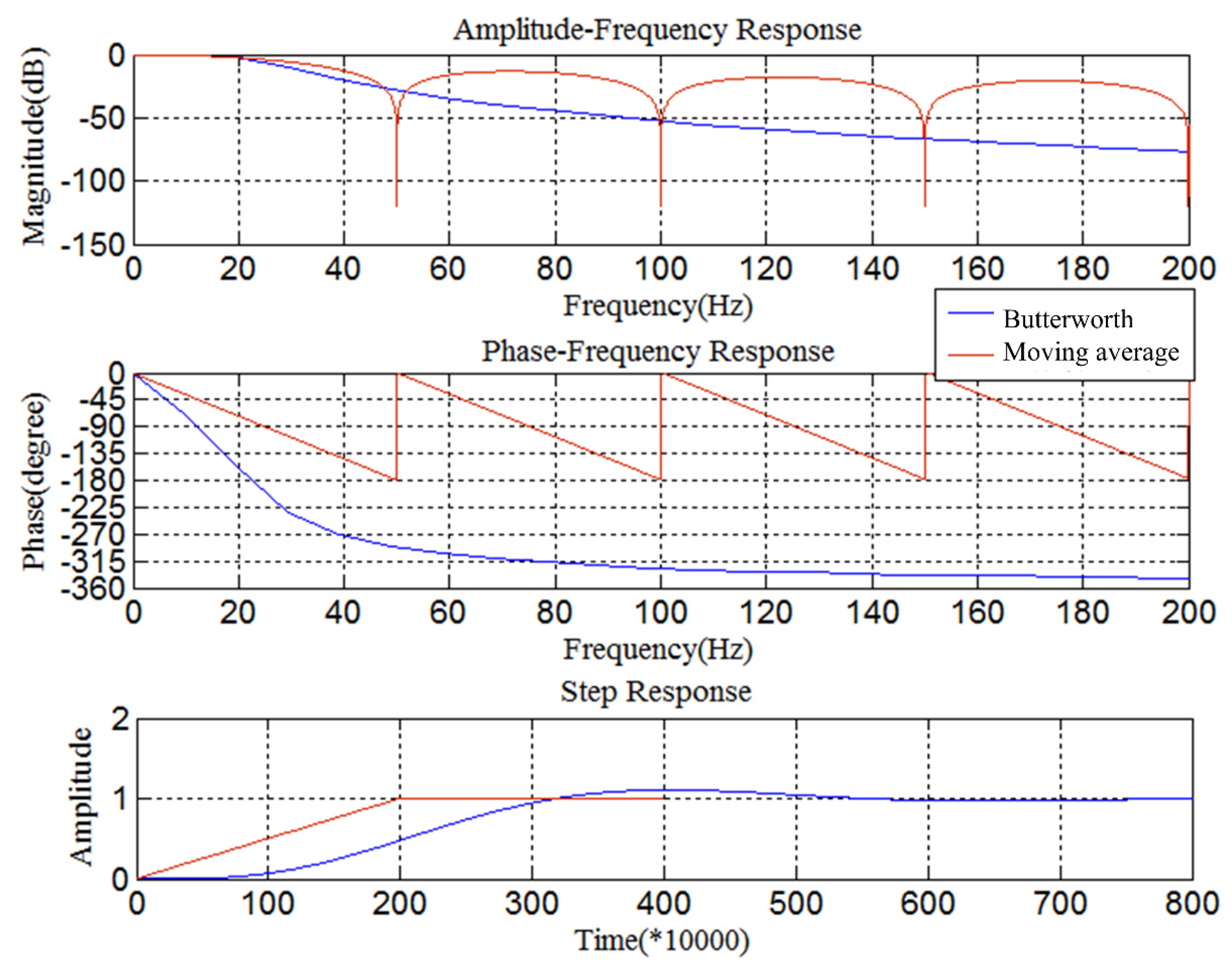
(a) Amplitude characteristic and (b) phase characteristic diagrams of ...
Bode Response of θr/h with Closed Inner Loop | Download Scientific Diagram