Please enter url.
Login
Logout
Please enter url.
9. Bode plot of a) frequency-control and b) phase-control loop gains ...
researchgate.net
source
Comments
6. Frequency response of velocity and current controller (Gm represents ...
Figure 2 from An Accurate Sense-FET-based Inductor Current Sensor with ...
Figure 1 from A Family of Two-Switch Boosting Switched-Capacitor ...
A comparison of gain diagrams of í µí°» 5 í µí± í µí± (í µí± ) and of ...
Energies | Free Full-Text | Improved Reactive Current Detection Method ...
Simulation and measurement results of the probe a Gain (dB) and phase ...
Sampled-Data Modeling and Stability Analysis of Digitally Controlled ...
1: Simulated wall SPL spectra and BF spectra for the acoustic ...
Theory and simulated frequency characteristics for the FDNC circuit of ...
SISO-OFDM simulation of COS companding method with LMMSE pre-equalizer ...
Electronics | Free Full-Text | Robust Terminal Sliding Mode Control on ...
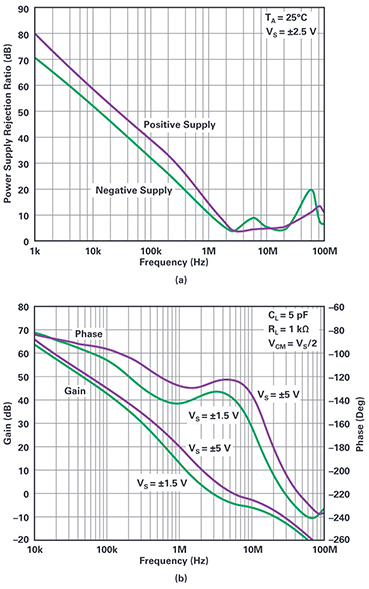
Bootstrapping a low voltage Op Amp to operate with high voltage sig...
Energies | Free Full-Text | Online Current Loop Tuning for Permanent ...
P-Vr characteristics of a generator in a large system for a very wide ...
Figure 1 from Low power LC-VCO design using direct cross-coupled cell ...
[PDF] A Single-Bit 2nd-Order CIFF Delta-Sigma Modulator for Precision ...
Figure 5 from A neural amplifier with high programmable gain and ...
Bode plots for Gbat$G_{bat}$ and GSC$G_{SC}$ | Download Scientific Diagram
Frequency Response of Power Stage | Download Scientific Diagram
Measured and fitted transfer functions (tip direction only) for small ...
Figure 1 from Control Design for Self-Servo Track Writing Using a State ...
Cole-Cole model fitting results of the complex permittivity for: a ...
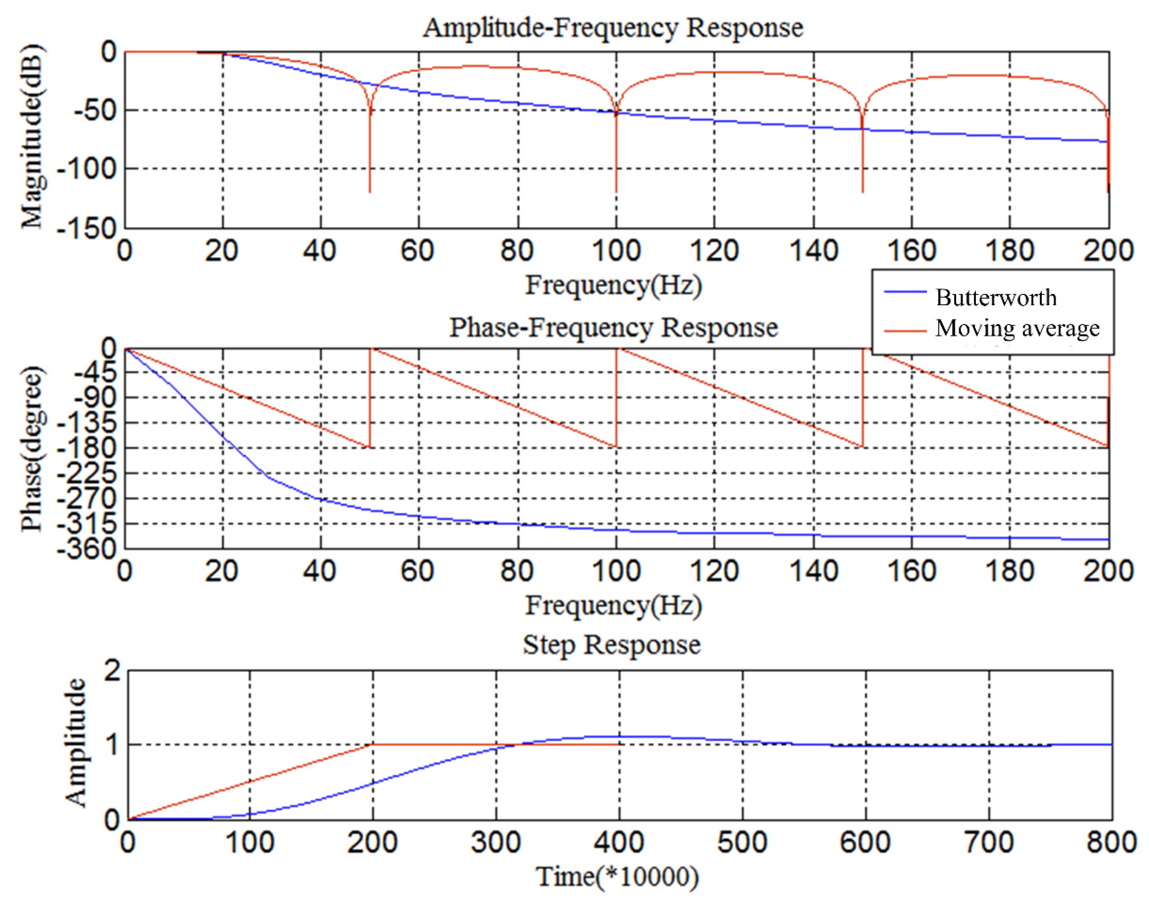
Frequency response by simulations using modified analysis and ...
Figure 1 from Vibration Sensors Using Power Generation with Electret ...
a Phase noise break down of PLL at 125 GHz frequency with -100, -89 and ...
The implemented LDO stability analysis by calculating both gain margin ...
Bode diagram of D(s) and Q(s) with different k (a) Bode diagram of D ...
Bode plot of DC m otor for a sampling ra te of 50 sam ples/second ...
Computed relative permeability of the six-turn toroidal inductor ...
Figure 1 from An Intra-Panel Interface With Clock-Embedded Differential ...
Loop impedances between the phase A and the sheath of the sector-shaped ...
Figure 1 from A Low-Power Self-Startup Bandgap Circuit for Energy ...
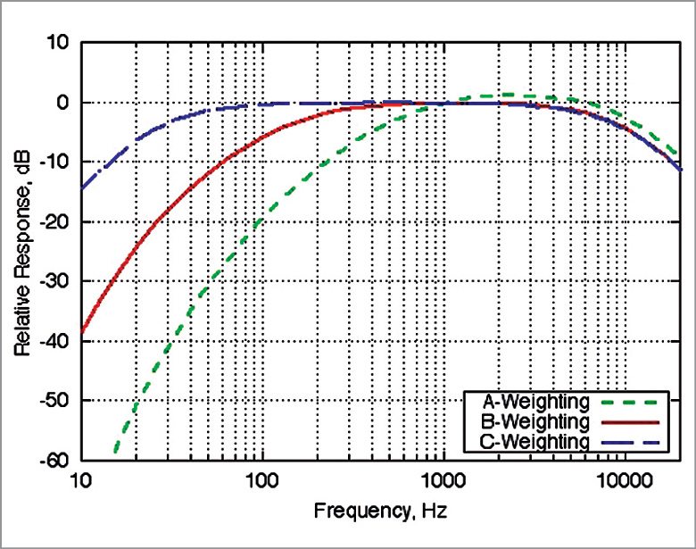
Choosing The Right Sound Level Meter
Annual and seasonal cumulative distributions of scintillation amplitude ...
Solved For the disk drive analysis - How are figures 8.52(a) | Chegg.com


![[PDF] A Single-Bit 2nd-Order CIFF Delta-Sigma Modulator for Precision ...](https://d3i71xaburhd42.cloudfront.net/dc82e07613b2d7f9db3b54c7e41f5154b8718d69/8-Figure9-1.png)