Please enter url.
Login
Logout
Please enter url.
Solved A Cmos Inverter Consists Of An Nmos And Pmos Trans Chegg Com ...
myxxgirl.com
source
Comments
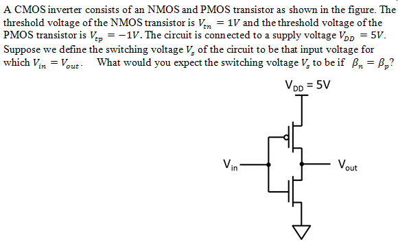
Solved A CMOS inverter consists of an NMOS and PMOS | Chegg.com
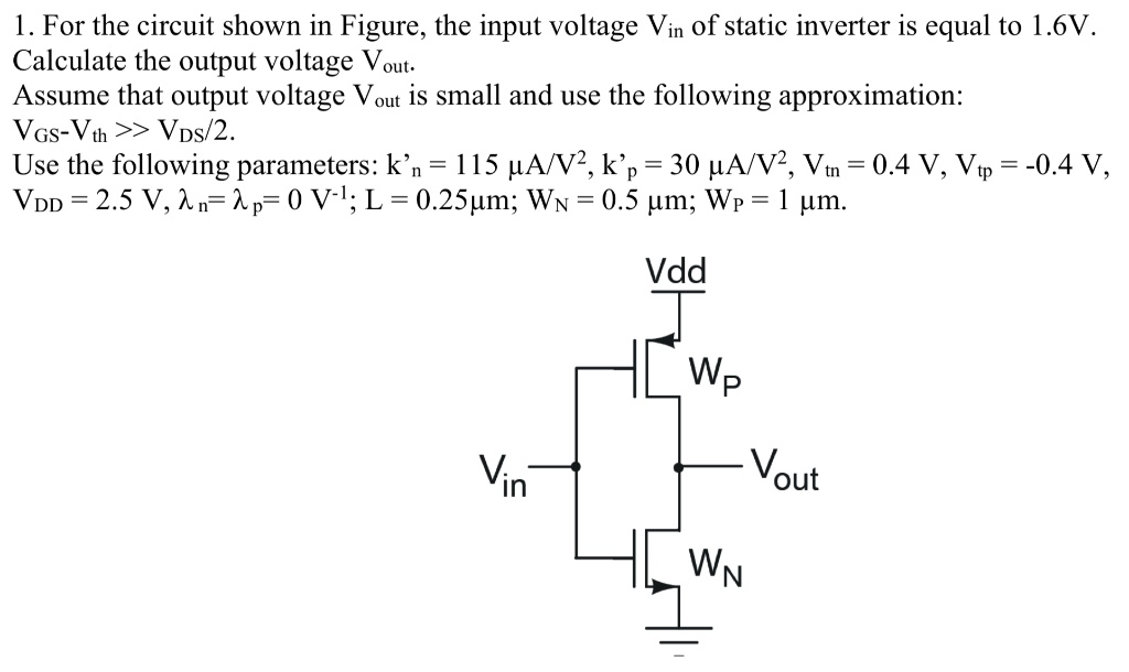
SOLVED: For the circuit shown in Figure, the input voltage Vin of the ...
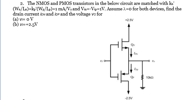
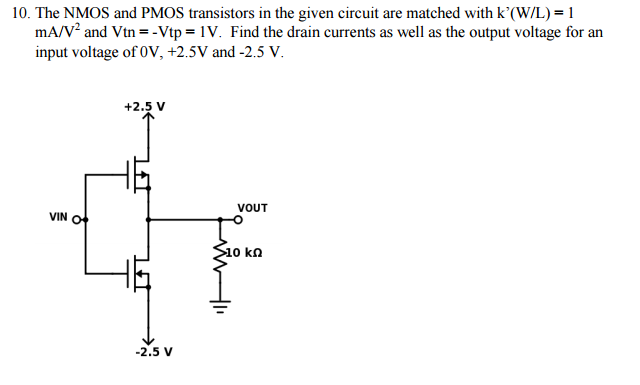
Solved The NMOS and PMOS transistors in the below circuit | Chegg.com
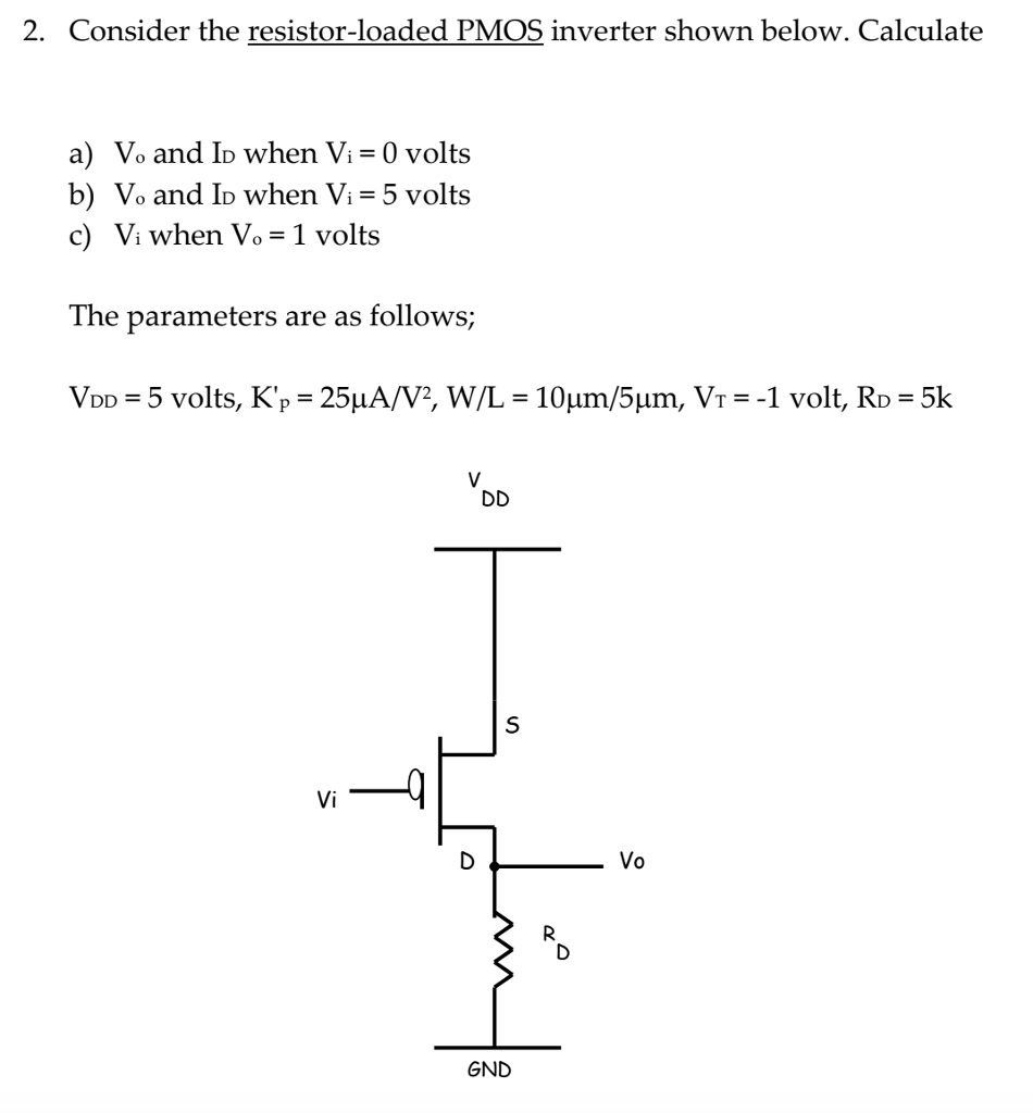
Solved 2. Consider the resistor-loaded PMOS inverter shown | Chegg.com
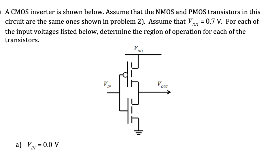
Solved DD A CMOS inverter is shown below. Assume that the | Chegg.com
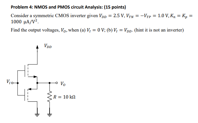
Solved Problem 4: NMOS and PMOS circuit Analysis: (15 | Chegg.com
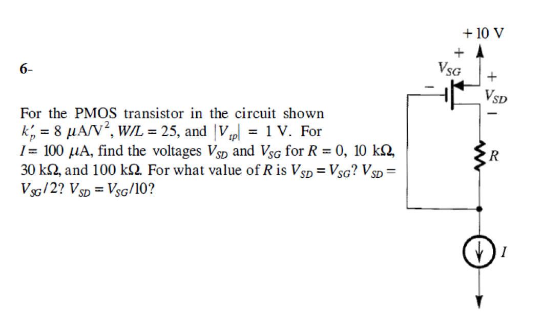
Solved + 10 V + A 6- VSG + VSD For the PMOS transistor in | Chegg.com
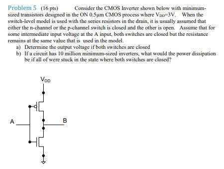
Solved Problem 5 (16 pts) Consider the CMOS Inverter shown | Chegg.com
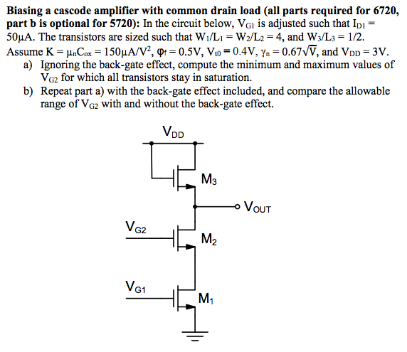
Solved Biasing a cascode amplifier with common drain load | Chegg.com
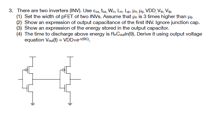
3. There are two inverters (INV). Use Eox, tox, Wn, | Chegg.com
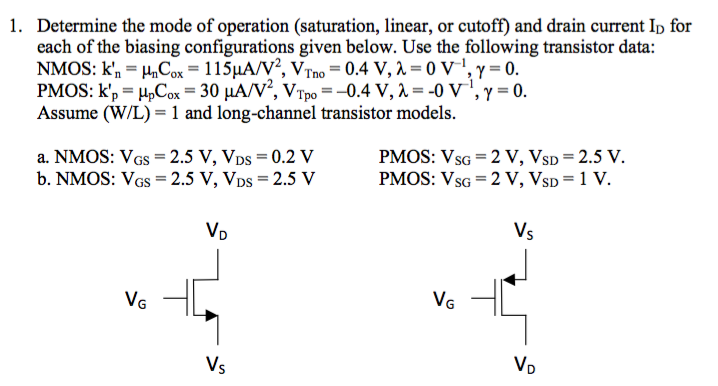
Solved Determine the mode of operation (saturation, linear, | Chegg.com
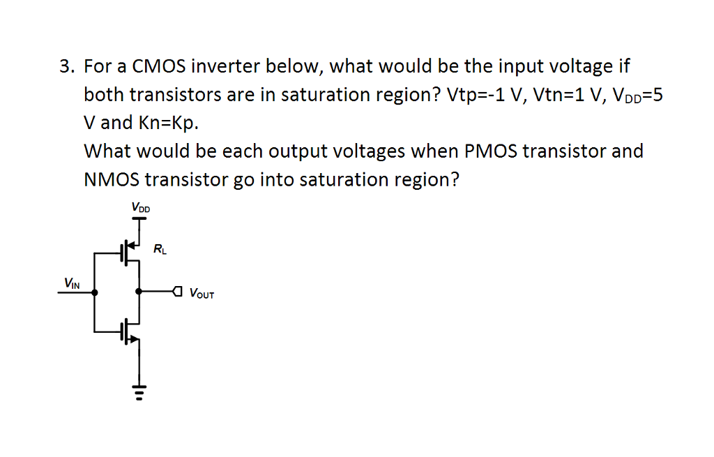
Solved For a CMOS inverter below, what would be the input | Chegg.com
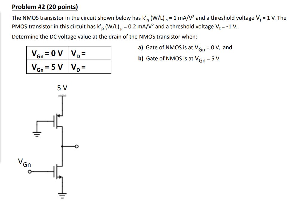
Solved Problem #2 (20 points) The NMOS transistor in the | Chegg.com
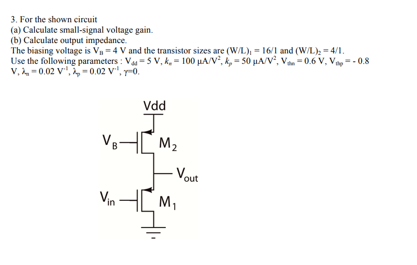
Solved 3. For the shown circuit (a) Calculate small-signal | Chegg.com
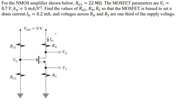
Solved For the NMOS amplifier shown below, RG1 = 22 M2. The | Chegg.com
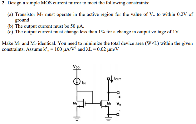
Solved 2. Design a simple MOS current mirror to meet the | Chegg.com
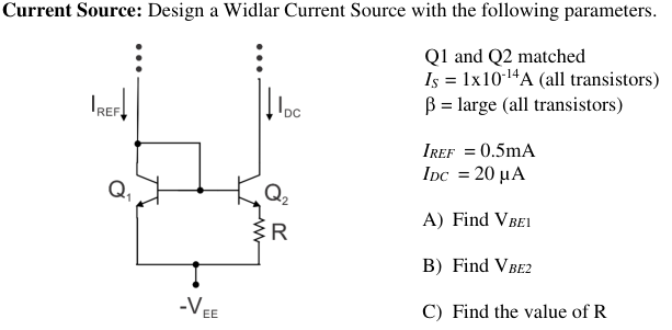
Solved Current Source: Design a Widlar Current Source with | Chegg.com
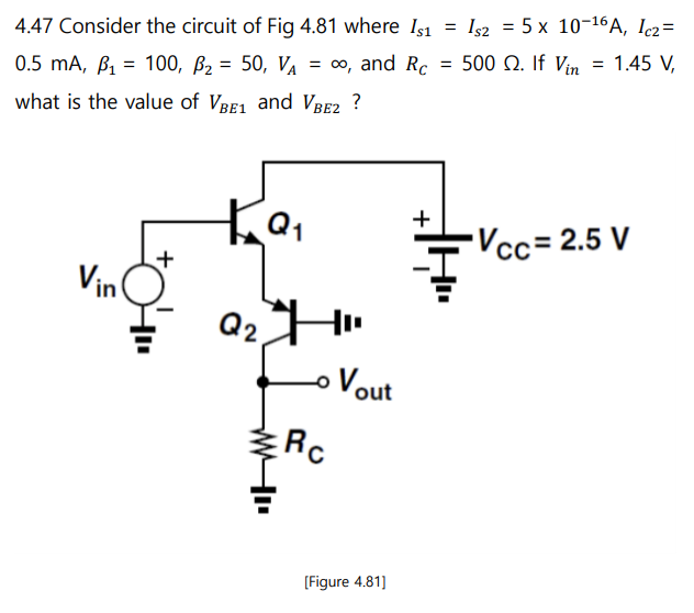
Solved 4 chapter - Bipolar transistor ( Razavi - | Chegg.com
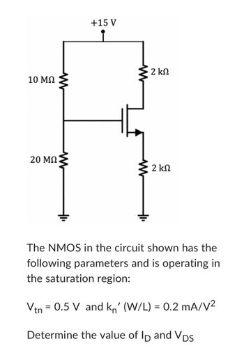
Answered: 10 ΜΩ 20 ΜΩ ww +15 V i 2 ΚΩ 2 ΚΩ The… | bartleby
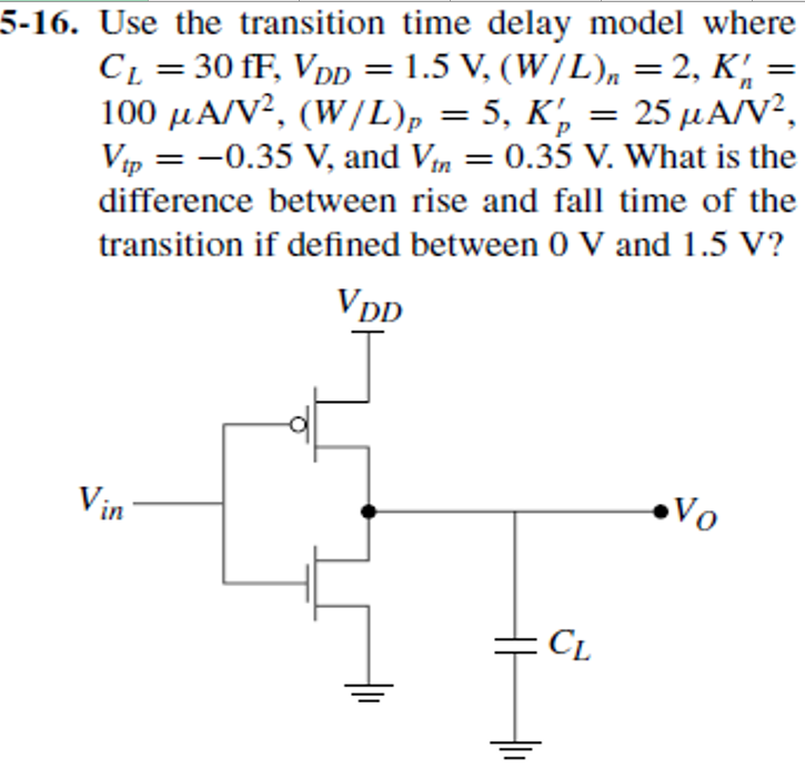
Solved 5-16. Use the transition time delay model where CL = | Chegg.com
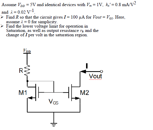
Solved Assume Vdd = 5V and identical devices with Vm = 1V. | Chegg.com
Answered: 5. Determine Vo in the circuit below in… | bartleby
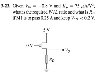
Solved Given Vtp = -0.8 V and Kp = 75 mu A/V2, what is the | Chegg.com
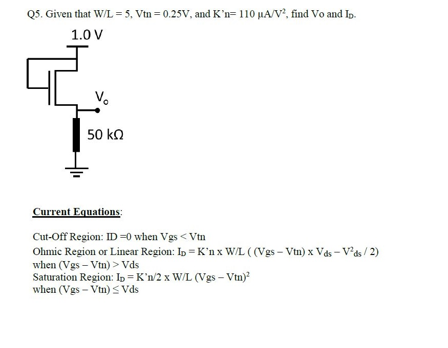
Solved Q5. Given that W/L = 5, Vtn = 0.25V, and K'n= | Chegg.com
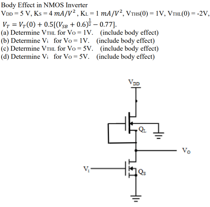
Body Effect in NMOS Inverter VDD = 5 V, Ks = 4 mA/V2, | Chegg.com
Solved The NMOS and PMOS transistors in the given circuit | Chegg.com
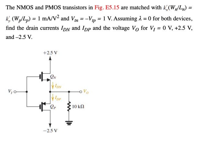
SOLVED: The NMOS and PMOS transistors in Fig. E5.15 are matched with k ...
Solved Considering the CMOS inverter shown in the figure | Chegg.com
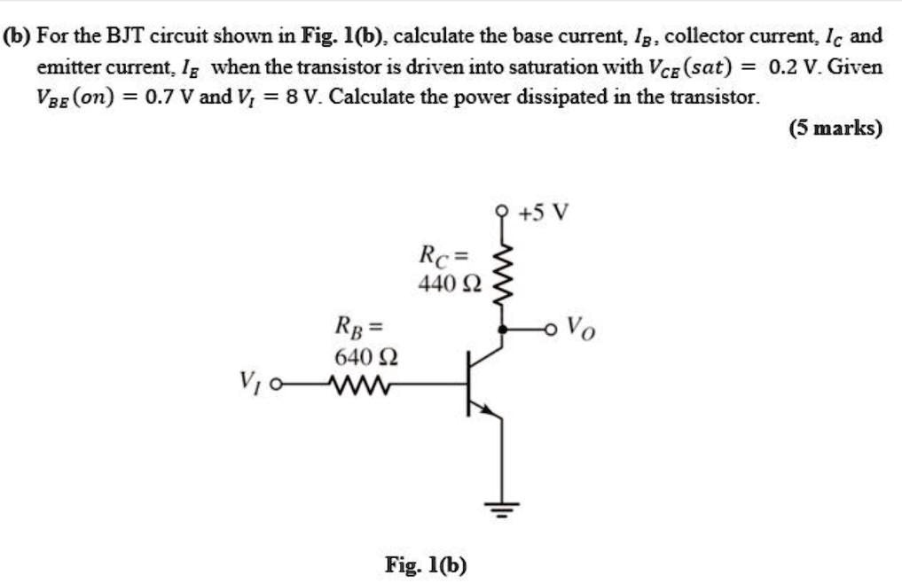
For the BJT circuit shown in Fig. 1b, calculate the base current (Ib ...
Solved 3. (20 points) The npn transistor in the circuit blow | Chegg.com
Solved JA pseudo-NMOS Inverter is utilizing FETs with the | Chegg.com
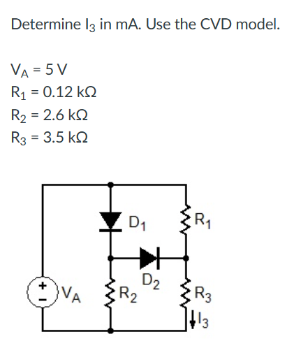
Solved Determine I3 in mA. Use the CVD model. VA=5 | Chegg.com
Solved VDD Q2 Vin Vout QI Please compute the voltage gain of | Chegg.com
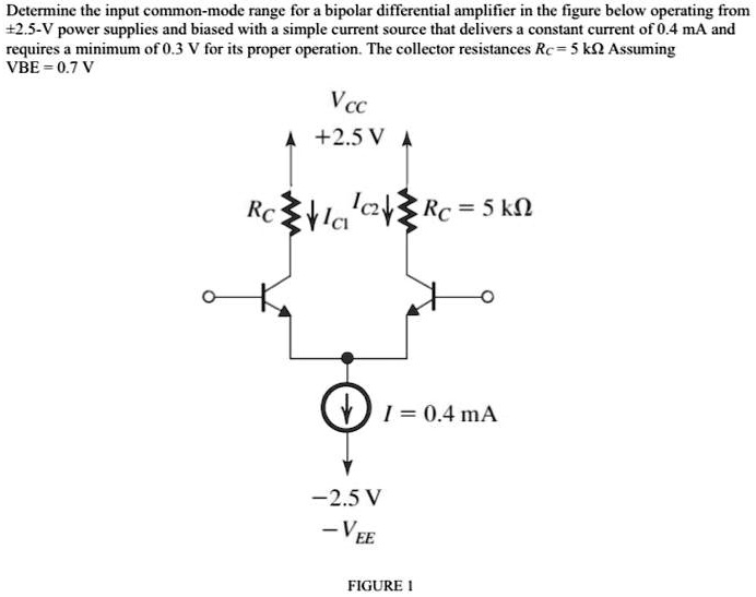
Determine the input common-mode range for a bipolar differential ...
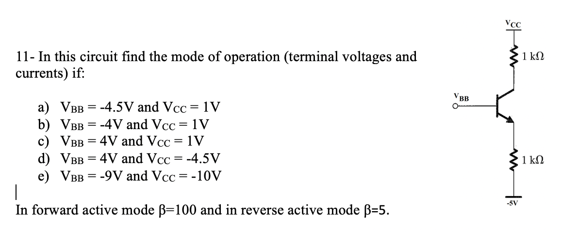
Solved 11- In this circuit find the mode of operation | Chegg.com
NMOS-PMOS-CMOS
PMOS-Inverter
NMOS-PMOS-Transistor
PMOS-Inverter-Circuit
Pseudo-NMOS-Inverter
CMOS-Inverter-VTC
MOS-FET-Inverter
NMOS-Logic-Gates
CMOS-Inverter-Layout
NMOS-Nand-Gate
PMOS-Diode
PMOS-Inverter-Diagram
CMOS-Inverter-On-Breadboard-PMOS-and-NMOS
CMOS-Transistor-Technology
NMOS-PMOS-Transistor-Symbols
PMOS-Inverter-vs-NMOS