Please enter url.
Login
Logout
Please enter url.
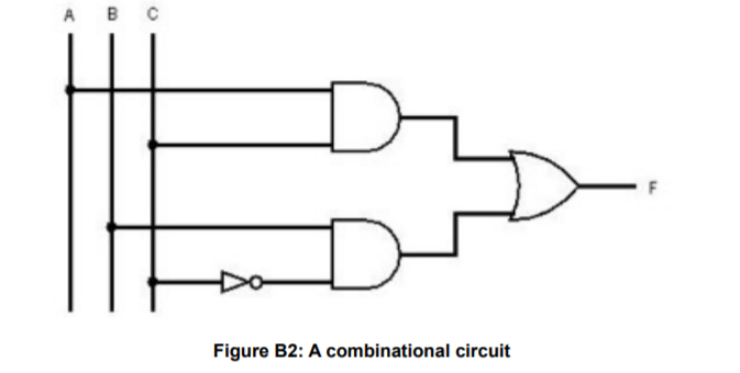
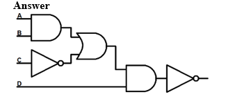
Solved Convert the combinational circuit of Figure B2 to a | Chegg.com
chegg.com
source
Comments
Solved Implement this this combinational circuit into | Chegg.com
# Question 1 (10 pt.). Given that each logic gate has | Chegg.com
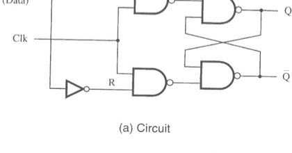
Solved: A circuit for a gated D latch is shown in Figure P7.7. Ass ...
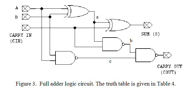
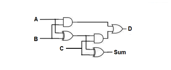
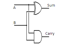
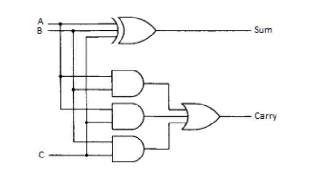
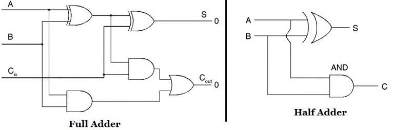
Half Adder and Full Adder Circuits with Truth Table
Verilog code for D Latch
Solved 2. Obtain the complete truth table for the circuit of | Chegg.com
Solved 4) Using a multiplexer design a circuit with a 4-bit | Chegg.com
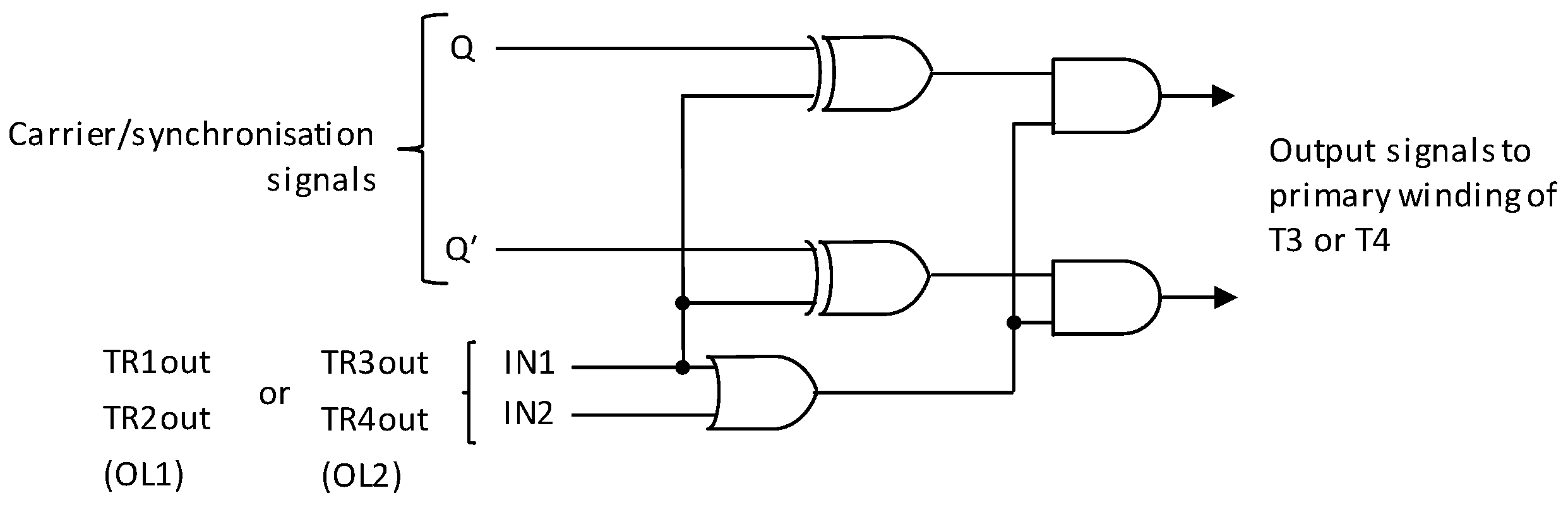
Energies | Free Full-Text | Gate Driver Circuit with All-Magnetic ...
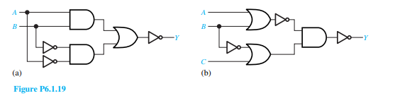
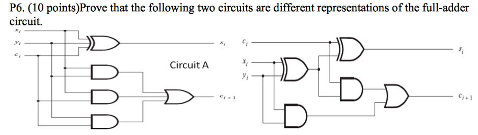
Solved Prove that the following two circuits are different | Chegg.com
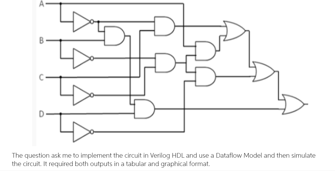
Solved can you show me step by step you use verilog hdl and | Chegg.com
FEEE - Fundamentals of Electrical Engineering and Electronics: Minterm ...
Multiplexer In Digital Electronics📋 📋
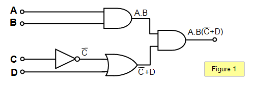
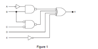
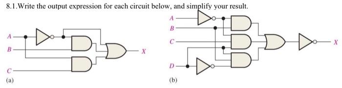
Solved 8.1.Write the output expression for each circuit | Chegg.com
Half Adder - Full Adder, truth table, Logic circuit - Electronics Club
Solved: Complete the timing diagram for the given circuit. Assume ...
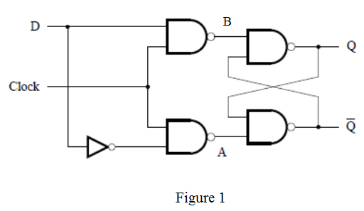
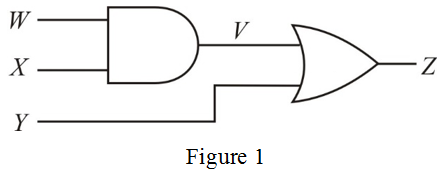
Solved Figure 1 D-Flip-flop with clock pulse (CP) Figure 1 | Chegg.com
[PDF] Buffered Steiner tree construction with wire sizing for ...
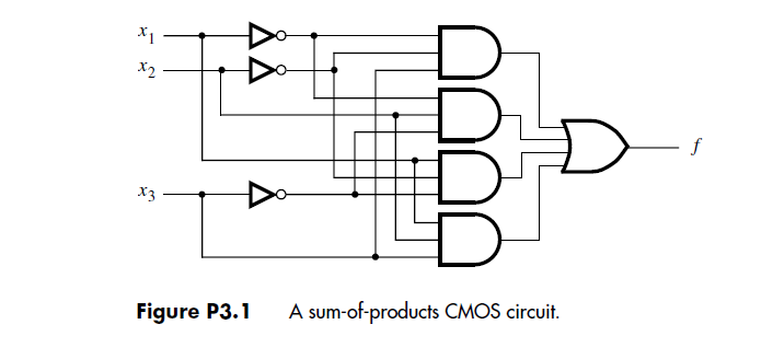
Solved Consider the circuit in Figure P3.1. Can this circuit | Chegg.com
Solved 1. Build and test a 1-bit full adder in Multisinm, | Chegg.com
Hardware-like X Propagation with Xprop - Verilog Pro
Chapter 6 – Flip-Flops, and Registers
Magnitude Comparator STLD/Digital Electronics - Care4you
Boolean algebra : Worksheet
schoolphysics ::Welcome::
ElectroBinary: Half Adder Verilog Code
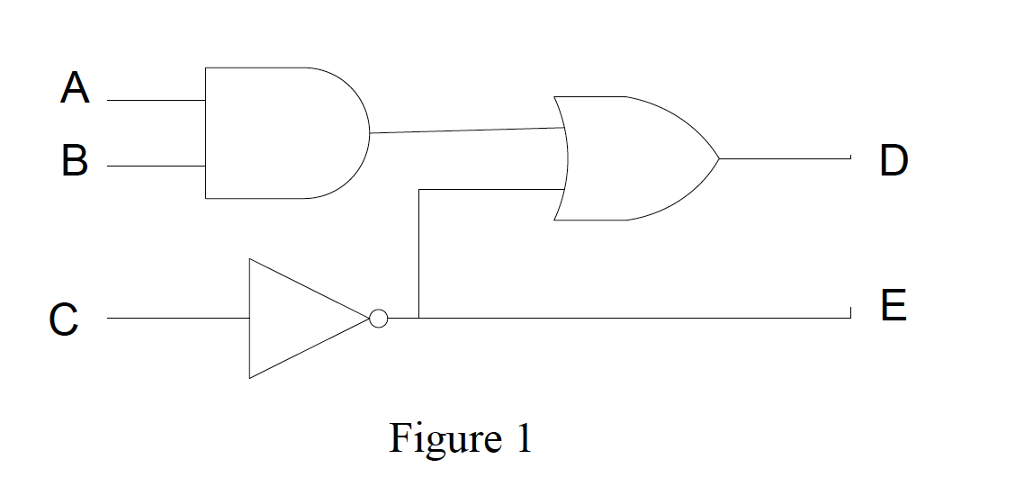
(Get Answer) - Obtain the Boolean expressions for the logic circuits ...
Solved Hi! I need help with the following: -With the Full | Chegg.com
Circuit de transistor Porte XOR
And-Or-Invert Circuit: a) at the gate level, b) CMOS implementation ...
Full Adder and Its Implementation - AK Academy
Adder Circuits STLD/Digital Electronics - Care4you
Solved B). Write a Verilog code that describes the following | Chegg.com
Solved Draw a timing diagram for the circuit in Figure | Chegg.com
Davide Gironi blog: A simple brushless sensored motor driver for AVR Atmega
How to design a circuit from NAND-gates only,using a truth-table ...


![[PDF] Buffered Steiner tree construction with wire sizing for ...](https://d3i71xaburhd42.cloudfront.net/9964082a1ccde97b8bdcb769d7f2b484f09692c8/3-Figure4-1.png)