Please enter url.
Login
Logout
Please enter url.
Schematic diagram of the liquid CO 2 extraction machine | Download ...
researchgate.net
source
Comments
Schematic diagram of the liquid CO 2 extraction machine | Download ...
Figure 1 from – 2 newsletter energy-saving strategies for Water-Source ...
How does exhaust air heating work? | ComfortZone™
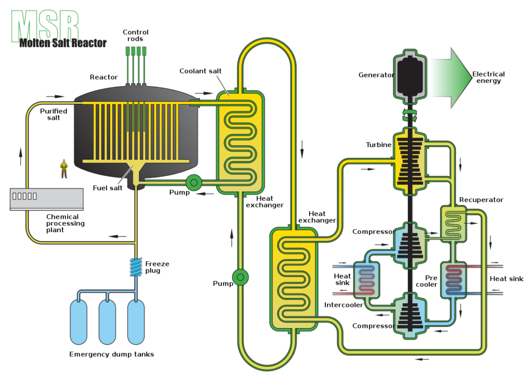
What is Thorium Salt Reactor? Based Nuclear Power | Linquip
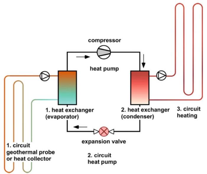
Solved 3. In warm places like Texas, shallow geothermal | Chegg.com
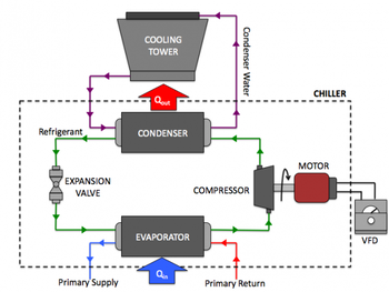
Water Cooled Chiller,Water Cooled Chiller System Manufacturer&Supplier
Schematic diagram of parallel compression cycle. [1] | Download ...
Tips for Improving Cooling Tower Efficiency - TRI-TECH ENERGY
Pump makers battle Green Deal exclusion | Process Engineering
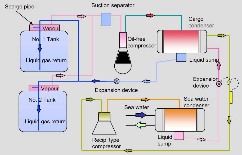
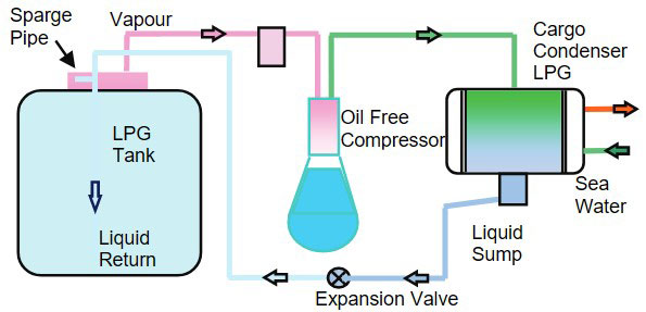
Design and Operation of the LPG Reliquefaction Plant
Salt Dewatering MVR Evaporator Enthalpy Increased High Temperature ...
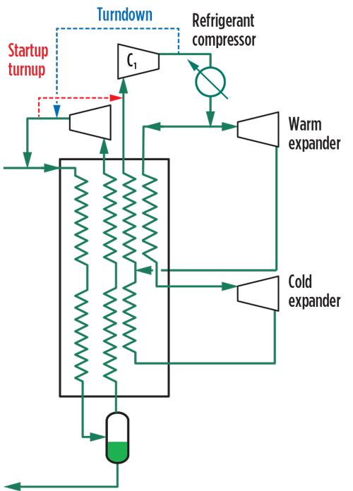
Innovations to reduce cost and schedule for small-scale LNG | Gas ...
Schematic diagram showing main components of a heat pump. | Download ...
Brine ground freezing system | Download Scientific Diagram
Schematic illustration and components layout of the refrigeration ...
Common Features | PRODUCTS | AIRSTAGE™ VRF Systems | FUJITSU GENERAL GLOBAL
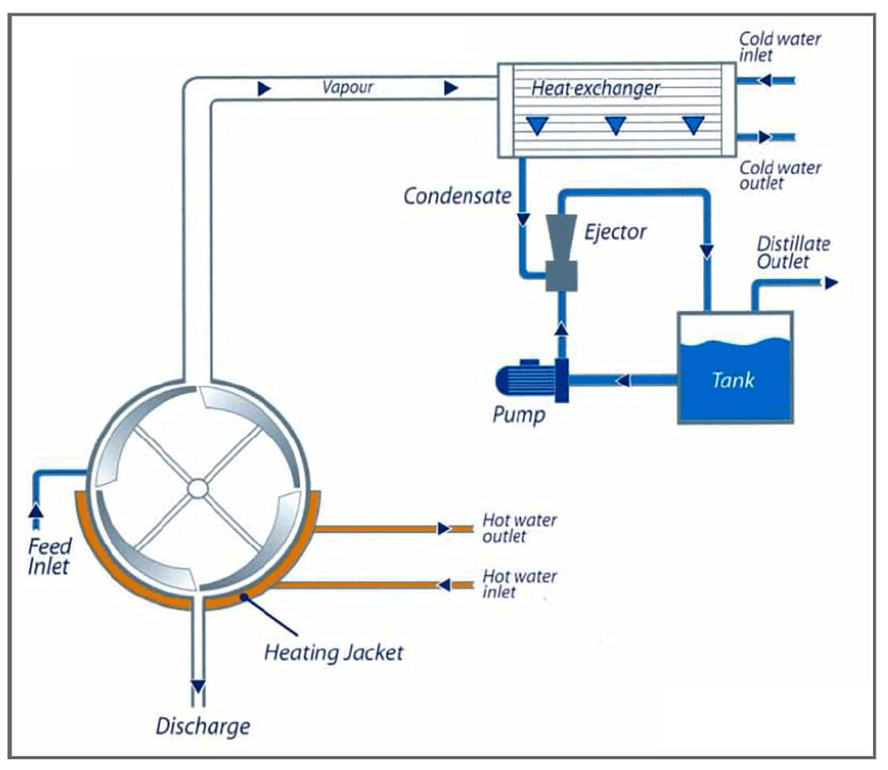
Blog: Evaporation Technology: A Unique Separation Process for ...
Heat Pump Water Heaters A Hot Commodity, But Not For Everyone | NW News ...
Schematic representation of the flow loop. Image adapted from Ref. [9 ...
[PDF] Design and simulation of a heat pump for simultaneous heating and ...
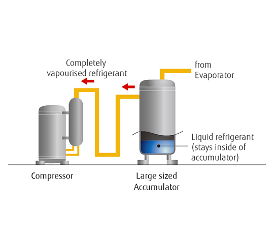
[DIAGRAM] Wiring Diagram Of Refrigeration System - MYDIAGRAM.ONLINE
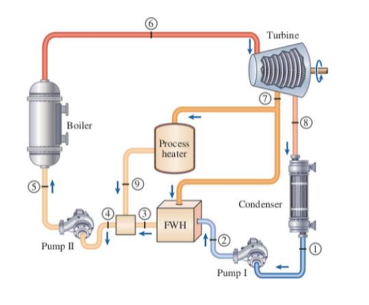
Solved Turbine Boiler Process heater -1 Condenser FWH Pump | Chegg.com
Northwest CHP Technical Assistance Partnership > About Clean Energy ...
Schematic representation of the flow loop used to test the discharge ...
-Schematic layout of a two-stage low-temperature refrigeration system ...
(PDF) Capillary Tube and Thermostatic Expansion Valve Comparative ...
Performance verification for catalytic material in fouling mitigation ...
Schematic representation of the HTHP | Download Scientific Diagram
Design and Operation of LPG Reliquefaction Plant
(a) Schematic diagram of RSCE concept; (b) Entropy diagram of RSCE ...
Refrigeration: April 2014
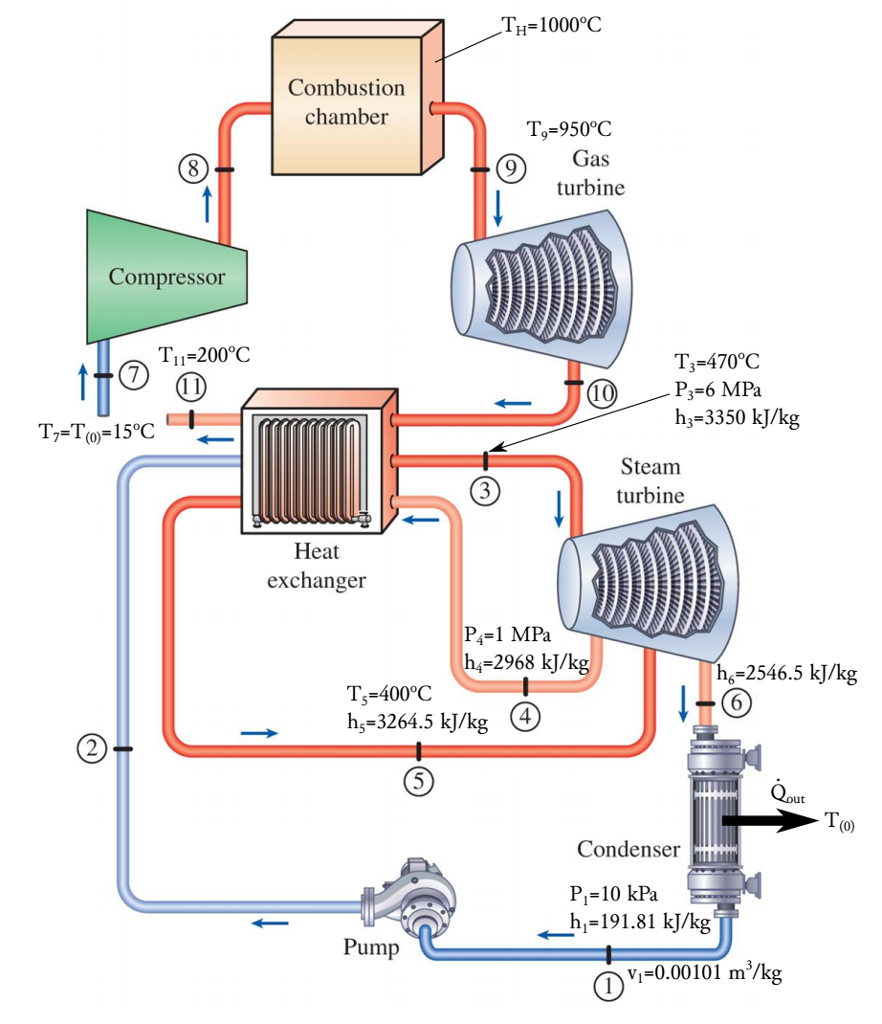
Solved 1. Combined gas-vapor power cycle Consider a combined | Chegg.com
Mapping COP for HFO-1336mzz(Z), HCFO-1233zd(E) and HCFO-1224yd(Z ...
A typical vapor-compression air-conditioning system (HVAC system design ...
Process Control and Automation of LNG Plant and Terminals


![Schematic diagram of parallel compression cycle. [1] | Download ...](https://www.researchgate.net/publication/352423876/figure/fig2/AS:1035178717741056@1623817247330/Schematic-diagram-of-parallel-compression-cycle-1.png)


![[PDF] Design and simulation of a heat pump for simultaneous heating and ...](https://d3i71xaburhd42.cloudfront.net/5867578ce0e00e95df1a4b9899b4eb7743fc28ca/500px/24-Figure1-1.png)
![[DIAGRAM] Wiring Diagram Of Refrigeration System - MYDIAGRAM.ONLINE](https://www.researchgate.net/publication/327030982/figure/fig1/AS:659753583779860@1534308920974/A-schematic-diagram-of-vapor-compression-refrigeration-system-with-a-subcool-unit.png)