Please enter url.
Login
Logout
Please enter url.
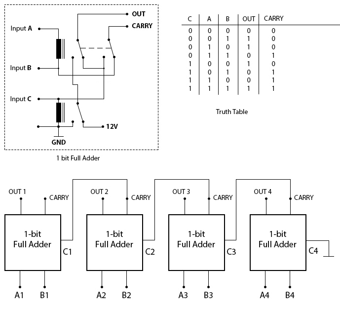
[DIAGRAM] Logic Diagram Of 4 Bit Ripple Carry Adder - MYDIAGRAM.ONLINE
mydiagram.online
source
Comments
[DIAGRAM] 8 Bit Adder Circuit Diagram - MYDIAGRAM.ONLINE
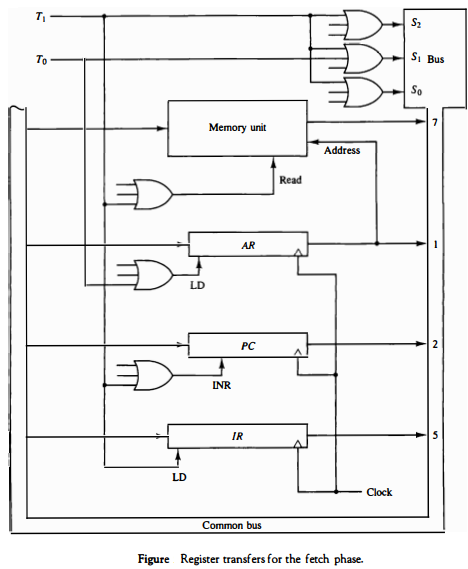
Computer Organization and Architecture (Instruction Cycle) - UPSC FEVER
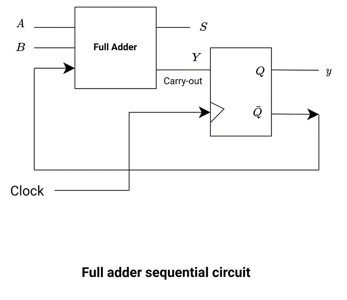
Block Diagram Of Full Adder Circuit
Carry-select adder | Semantic Scholar
OCTAVO
Figure A.4: Wallace tree adder. The picture is taken from... | Download ...
(PDF) Area Efficient Rapid Signal Acquisition scheme for High Doppler ...
Radix-4 butterfly unit. 10 R4 unit. All R4 units in the same stage are ...
Internal circuit of one slice of ALU | Download Scientific Diagram
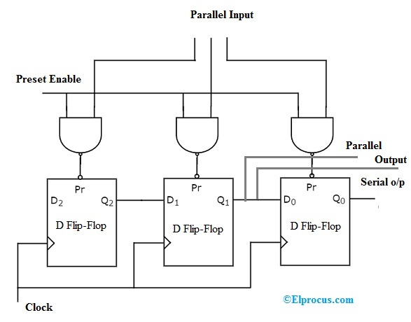
Shift Register : Different Types, Counters and Applications
Modified Booth Multiplier with Carry Select Adder using 3-stage ...
4 bit relay computer – AntiMath
Figure 2 from Design of efficient totally self-checking checkers for m ...
Diagram of control logic of 3-stage CCP gain-stage. | Download ...
Principles of computer architecture - arithmetic
Combinational and sequential design of a 4-bit Adder. (a) HA circuit ...
Solved Gate level Verilog Have to rewrite the code by | Chegg.com
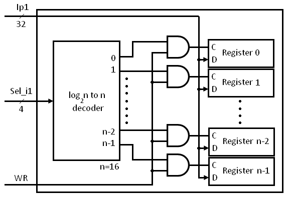
Solved Use 1-bit D-Flipops to build a 16-bit register with | Chegg.com
2: Block diagram of an iterative receiver with PIC-STD. | Download ...
Schematic representation of PSM Controller. | Download Scientific Diagram
Solved 9.15 [M] Delay in multiplier arrays is investigated | Chegg.com
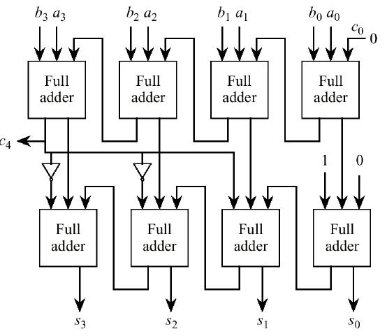
Circuit Diagram Of 4 Bit Adder Subtractor Using Ic 7483 » Wiring Core
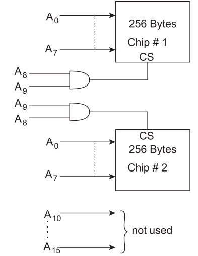
What memory address range is NOT represented by chip #1
Figure A.3: Optimized column of the add-stepper multiplier. | Download ...
20+ full adder block diagram - OvitaDenayah
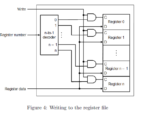
Verilog for Beginners: Register File
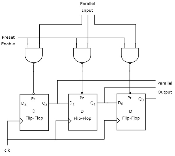
4-bit Shift Register Using D Flip Flop
Difference between Sequential and Combinational Circuit - HardwareBee
bit conditional sum adder | Download Scientific Diagram
Figure 2 from A low-voltage, Low-Power 4-bit BCD adder, designed using ...
Link between Combinational Logic and Sequential Logic - Electrical ...
Proposed approximate 4:2 compressor. (a) Gate‐level circuit. (b ...
Digital Circuits - Shift Registers | PadaKuu.com
VALVE encoder block diagram. The figure shows three segments: 32-bit ...
LUT partitioning technique for 4-taps FIR filter Re-writing the value ...


![Solved 9.15 [M] Delay in multiplier arrays is investigated | Chegg.com](https://d2vlcm61l7u1fs.cloudfront.net/media/af4/af40edad-dd51-44b7-90e4-52e061f46e41/phpBL9kQr.png)