


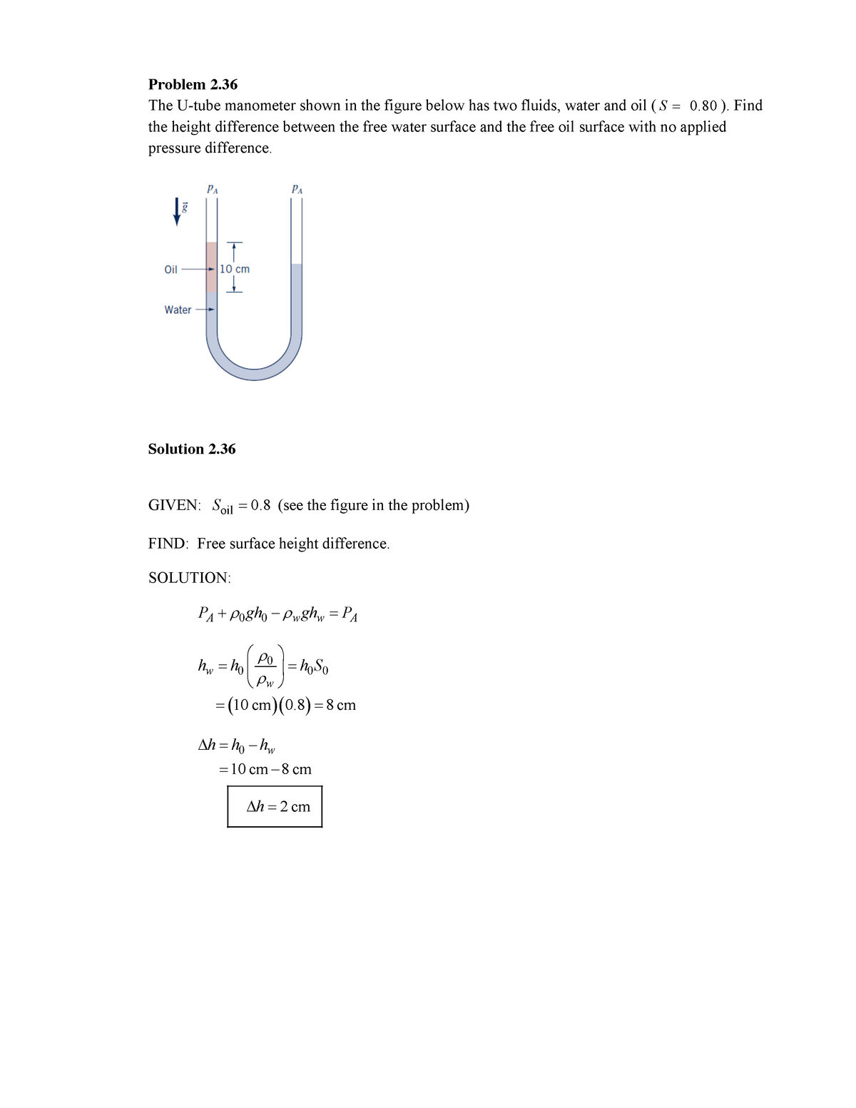
![[SOLVED] The U - tube manometer shown in the figure below has | SolutionInn](https://dsd5zvtm8ll6.cloudfront.net/si.experts.images/questions/2025/01/679cd8044b1a7_163679cd803a1be7.jpg)


![[SOLVED] A U-tube manometer consists of two tubes A and B, with (1 ...](https://dsd5zvtm8ll6.cloudfront.net/si.experts.images/questions/2023/01/63bba3794650a_1673241465000.jpg)


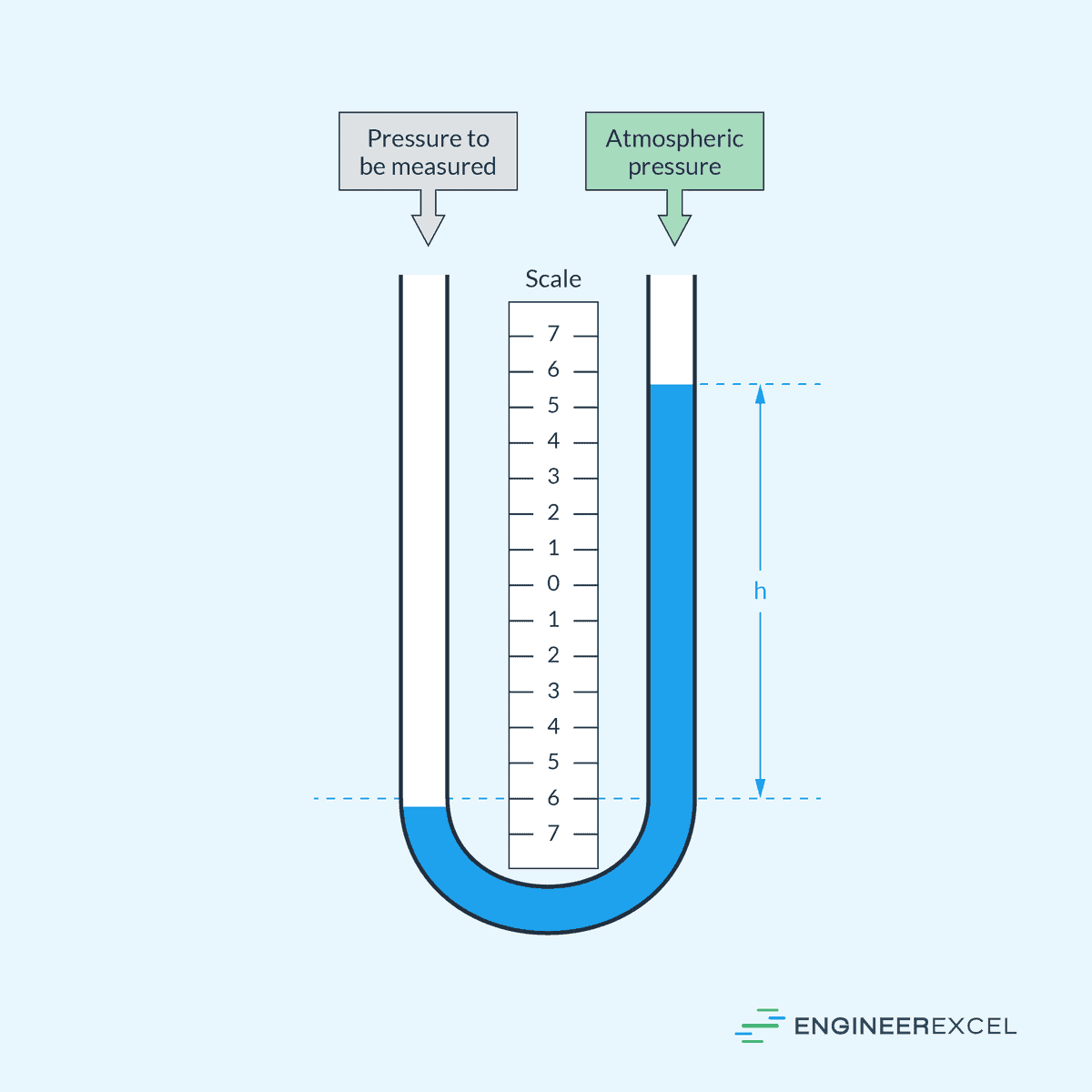
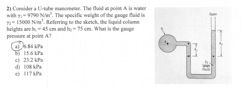
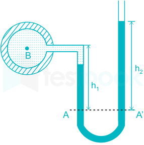
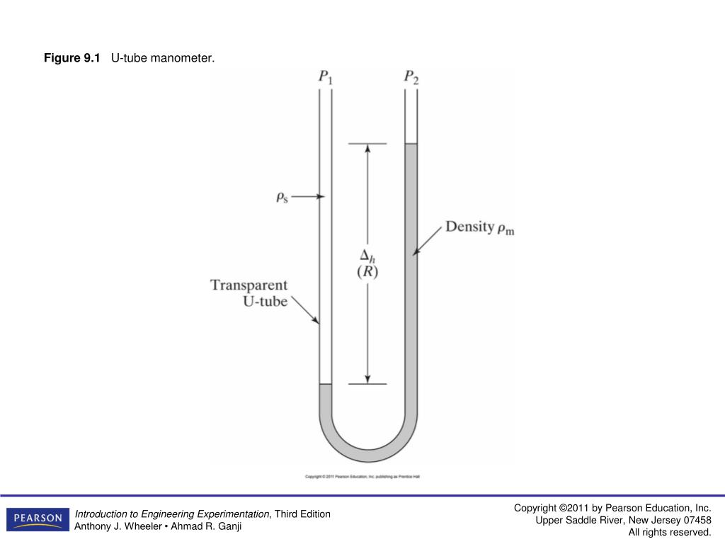
Experience the pulse of problem 9.1: consider a vertical u-tube manometer, as shown in fig. 9 with our extensive urban gallery of substantial collections of images. highlighting the diversity of photography, images, and pictures in urban settings. ideal for architectural and street photography. Discover high-resolution problem 9.1: consider a vertical u-tube manometer, as shown in fig. 9 images optimized for various applications. Suitable for various applications including web design, social media, personal projects, and digital content creation All problem 9.1: consider a vertical u-tube manometer, as shown in fig. 9 images are available in high resolution with professional-grade quality, optimized for both digital and print applications, and include comprehensive metadata for easy organization and usage. Discover the perfect problem 9.1: consider a vertical u-tube manometer, as shown in fig. 9 images to enhance your visual communication needs. Professional licensing options accommodate both commercial and educational usage requirements. Whether for commercial projects or personal use, our problem 9.1: consider a vertical u-tube manometer, as shown in fig. 9 collection delivers consistent excellence. Advanced search capabilities make finding the perfect problem 9.1: consider a vertical u-tube manometer, as shown in fig. 9 image effortless and efficient. Diverse style options within the problem 9.1: consider a vertical u-tube manometer, as shown in fig. 9 collection suit various aesthetic preferences.