Please enter url.
Login
Logout
Please enter url.
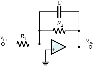
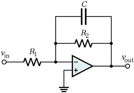
Low Pass Filter Circuit Schematic
usermanualsnifting.z21.web.core.windows.net
source
Comments
Active low pass filter circuit | Download Scientific Diagram
Active Low Pass Filter : Overview, Types, LPF using Op-Amp & Uses
(a) Single-stage folded-cascode integrator opamp (b) Two-stage class AB ...
Voltage to current converter with floating load. | Download Scientific ...
Implemented circuit for a Type II linear compensator. | Download ...
Schematic of the active loop filter, applying the differential output ...
Voltage to Current Converter
Gate EC-2010 Question Paper With Solutions | Page 10 of 65 | Electrical4u
Negative impedance converter | Negativity, Circuit, Physics
SOLVED: Find an expression for the voltage transfer ratio for the ...
In the circuit shown, the op-amp has finite input impedance, infinite ...
Automatic Control Systems Section 2 - Electronics and Communication ...
Operational Amplifier and Amplifier Models | SpringerLink
Sallen-key band-pass filter circuit | Download Scientific Diagram
Butterworth filter - Wikipedia | Butterworth, Filters, Wikipedia
Audio Shelving EQ: What Are Low Shelf & High Shelf Filters?
Review of the Op-Amp Integrator - Video Tutorial
Nominal value of resistor R1 = k ohms, Measured value | Chegg.com
The second order high-pass filter. | Download Scientific Diagram
Assuming that the op amp in the circuit shown is ideal. The output ...
4.2: NON-INVERTING AMPLIFIER | GlobalSpec
Operational Amplifier Explained with Integrator and Differentiator
Solved A circuit in the non-inverting amplifier | Chegg.com
Non-inverting amplifier | Electronics Tutorial
Solved If R1 = 5R2 = R3, what is the gain Vout/Vin, of the | Chegg.com
Micromachines | Free Full-Text | A High-Accuracy RC Time Constant Auto ...
A Continuous-Time Sigma-Delta Modulator with a Hybrid Loop Filter and ...
Solved: Part A Part Complete Select The Correct Circuit Di... | Chegg.com
Assuming that the op amp in the circuit shown is ideal,The output ...
Schematic Diagram Of Wein Bridge Oscillator - Circuit Diagram
Solved This op-amp circuit uses a filter (lead-lag) to | Chegg.com
Using Op Amps as Analog Integrators | DigiKey
Solved Determine the closed-loop voltage gain of the circuit | Chegg.com
Solved: (a) Design a second-order high-pass Butterworth filter ...
Band-Pass-Filter-Circuit-Diagram
Low-Pass-Filter-Block-Diagram
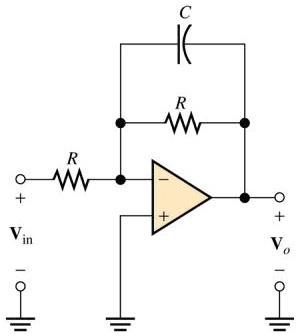
Low-Pass-Filter-Op-Amp
Low-Pass-Filter-RL-Circuit
Band-Pass-Filter-Circuit-Design
Active-Low-Pass-Filter
Low-Pass-RC-Circuit
Low-Pass-Filter-Oscilloscope
Low-Pass-Filter-Schematic
RLC-Low-Pass-Filter
Simple-Low-Pass-Filter-Circuit
All-Pass-Filter-Circuit
High-Pass-Filter-Circuit
Passive-Low-Pass-Filter-Circuit
1st-Order-Low-Pass-Filter
Digital-Low-Pass-Filter