Please enter url.
Login
Logout
Please enter url.
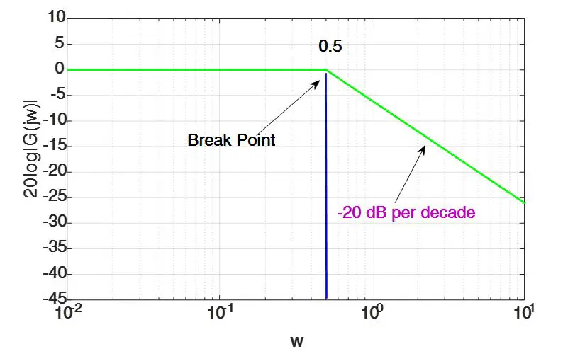
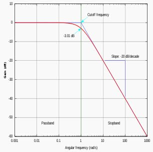
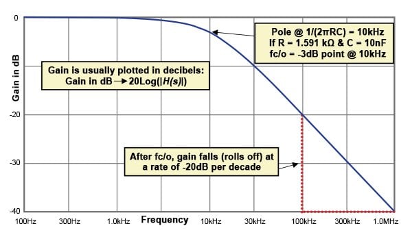
Asymptotic Bode Diagram
schematiclistneustadt.z19.web.core.windows.net
source
Comments
Bode Plot Example | Bode Diagram Example MATLAB | Electrical Academia
Bode Plot Example MATLAB | Electrical Academia
Vibration response signals of microcantilevers a microcantilever 1# and ...
Neural amplifier frequency response | Download Scientific Diagram
17 Frequency Response of Amplifiers - conocimientos.com.ve ...
(PDF) Closed Loop Identification Of A First Order Plus Dead Time ...
Ygraph - Share Your Graph! Search for a graph, chart, diagram ...
The bode plot of the transfer function (22) with and without full ...
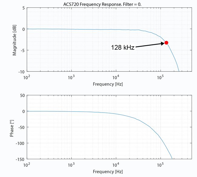
System Bandwidth in Complex Current Sensor Applications
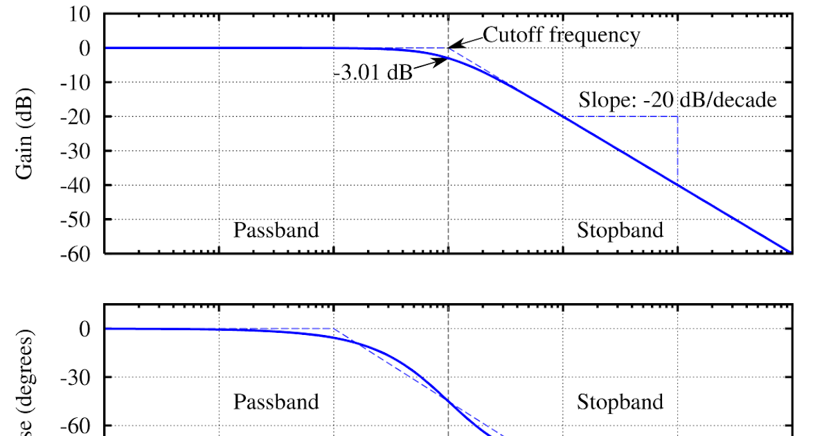
Low-pass Butterworth filter frequency response with cut-off frequency ...
Sensors | Free Full-Text | Research on the Signal Process of a Bell ...
Understanding Cutoff Frequency: What it is and How it Affects Your ...
Noise cancellation technique in the CS amplifier | Download Scientific ...
Simulated phase noise (at 9.992 GHz) of the push‐push oscillator with ...
Conversion Gain Improvement of InP/InGaAs HBT Opto-Electronic Mixer ...
Bode plot of 10th order bessel low pass filter circuit | Download ...
Inner loop bode plot and cutoff frequency. | Download Scientific Diagram
17 Frequency Response of Amplifiers - conocimientos.com.ve: Frequency ...
(a) PSO algorithm flow chart. (b) B-D optimized telescopic OTA gain and ...
Calculated transfer function of the PLL. | Download Scientific Diagram
Simulated phase noise of the VCO. | Download Scientific Diagram
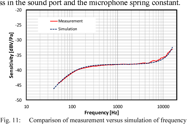
Figure 11 from Design of a poly silicon MEMS microphone for high signal ...
The open-loop Bode plot of the system. (a)Kv = 1, (b)Kv = 33.9 ...
Electrical Filters: An Introduction to filter types & topologies ...
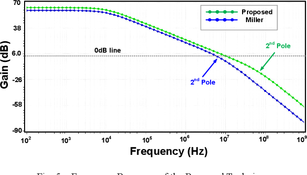
Figure 1 from A Low Power Miller Compensation Technique for Two Stage ...
Frequency and phase-encoding in k-space | Download Scientific Diagram
Stability analysis of the non-Foster matching impedance. (a) Simulation ...
Frequency response amplitude and phase of the Balun circuit simulated ...
Impedance curve of the passive elements (a) Test inductor, (b) CM ...
Biricha Lecture Notes on Analog and Digital Power Supply Design Part 1C ...
What is the decibel voltage gain when $f=20 \mathrm{kHz}$? W | Quizlet
PM eddy-current losses for Iq = 1 A and the 2D and 3D reference meshes ...
laplace transform - How do I find a controller for non-minimum phase ...
Antragsteller dominieren schwanken butterworth filter phase shift ...
5 The definition of reverberation time (after [9.4]) | Download ...
Bode-Plot-Graph
Bode-Plot-Examples
Bode-Plot-Paper
Nyquist-Plot
Bode-Plot-Formula
Root-Locus
Low-Pass-Bode-Plot
Blank-Bode-Plot
Phase-Plot
High-Pass-Bode-Plot
Integrator-Bode-Plot
Bode-Plot-Axis
First-Order-Bode-Plot
Nyquist-and-Bode-Plots
Bode-Plot-Graph-PDF
Bode-Chart


![5 The definition of reverberation time (after [9.4]) | Download ...](https://www.researchgate.net/profile/Anders-Gade-3/publication/234546709/figure/fig3/AS:11431281079785460@1660851939067/The-definition-of-reverberation-time-after-94_Q640.jpg)