Please enter url.
Login
Logout
Please enter url.
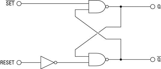
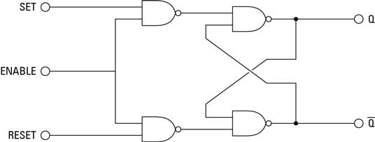
D Latch Circuit Diagram
userdatamathilda.z1.web.core.windows.net
source
Comments
Electronics Basics: What is a Latch Circuit - dummies
Electronics Basics: What is a Latch Circuit - dummies
S1#36--analysis of 3-state disabled gates
The AC Volt | Nuts & Volts Magazine
Simple Latch Circuit Diagram | Electronic Circuit Diagrams & Schematics
Logic Level Shifters for Driving LED Strips – Electric Fire Design
Folded cascode with NMOS input structure (a) complete circuit, (b) half ...
Electronics Projects: How to Build a Latch Circuit - dummies
Preamplifier schematic | Download Scientific Diagram
Inside Intel's first product: the 3101 RAM chip held just 64 bits
Insulated Gate Field-Effect Transistors Worksheet - Discrete ...
6: NOR latch, block diagram and excitation requirements for SR flip ...
Schematic of a single stage of an R-2R DAC. In this design, the ...
Design_of_Low-Power_CMOS_Cell_Structures_Using_Subthreshold_Conduction ...
Ring amplifier in unity gain closed loop inverting configuration ...
MOSFET driver for digitally controlled, battery powered boost converter ...
(a) Schematic of NAND2 gate. (b) Input and output waveforms for GNRFET ...
High-Speed MOSFET Gate Drivers - EEWeb
Solutions and application areas of flip-flop metastability | Semantic ...
Edge Triggered D Flip Flop Circuit Diagram - Circuit Diagram
Page 2, Audio Amplifiers.
DIY RAM Memory- Register Style : 4 Steps (with Pictures) - Instructables
Example of an adder evolved on a 3x3 grid. | Download Scientific Diagram
Cascode Current Mirror with voltage headroom consumed. | Download ...
Block diagram of 512-bit synchronous EEPROM | Download Scientific Diagram
Electronics Basics: What is a Gated Latch - dummies
Basic BJT current mirror : ... so the collector-base voltage of Q2 is ...
Phoenix Contact 2964319 DEK-TR/INV Inverter module (PNP to NPN. NPN to ...
A level conversion circuit proposed in [7] (LC2). | Download Scientific ...
Circuit of a single stage. | Download Scientific Diagram
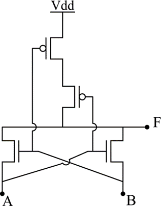
In the circuit shown, A and B are the inputs and F is the output. What ...
(a) Static CMOS XOR (b) Static CMOS AND gates 3.2. PTL based XOR and ...
Analog Intuition (GATE & VLSI) : Trans Linear Circuits-2
MOS CIRCUITS Android App
(a) FIFO controller, (b) Specification, (c) Specification with state ...
Simple-Latch-Circuit
Latch-Diagram
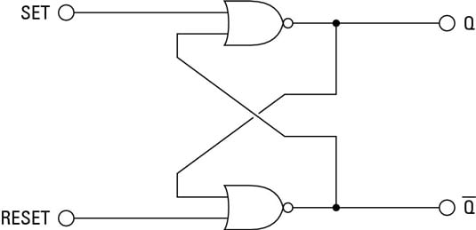
Sr-Latch-Circuit
SR-Latch-Schematic
Transistor-Latch-Circuit
Latch-Relay-Circuit
Soft-Latch-Circuit
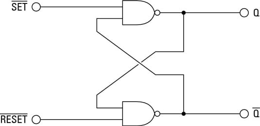
RS-Latch-Circuit
Latch-Logic-Circuit
Flip-Flop-Latch-Circuit
Latch-Switch-Circuit
D-Latch-Diagram
555-Timer-Latch-Circuit
Digital-Latch-Circuit
FET-Latch-Circuit
T-Latch-Circuit-Diagram


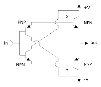


![A level conversion circuit proposed in [7] (LC2). | Download Scientific ...](https://www.researchgate.net/profile/Sherif-Tawfik/publication/224714404/figure/fig2/AS:652950674358280@1532686980664/The-standard-level-converter-circuit-LC1_Q640.jpg)