Please enter url.
Login
Logout
Please enter url.
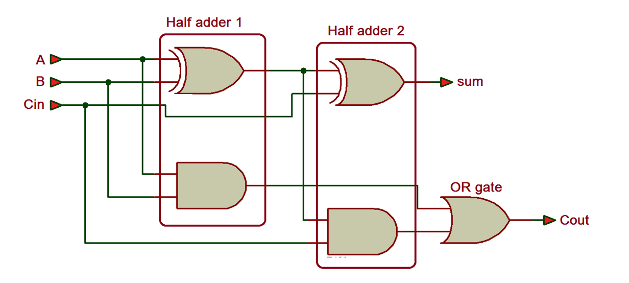
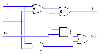
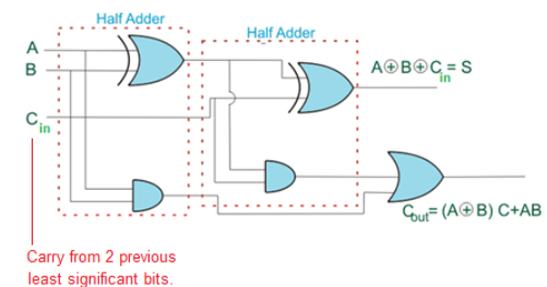
Explain Half Adder Circuit With Diagram
guidedbkoch.z19.web.core.windows.net
source
Comments
VHDL Tutorial – 10: Designing half and full-adder circuits
Digital Logic: Digital logic
Solved For the Adder circuit given below. Show the logic | Chegg.com
Digital Electronics Laboratory
Tech Funda of the Day: LFSR - Linear Feedback Shift Registers
Synopsys ASIC Design Interview Questions | vlsi4freshers
CS 641 Lecture
Lab 6
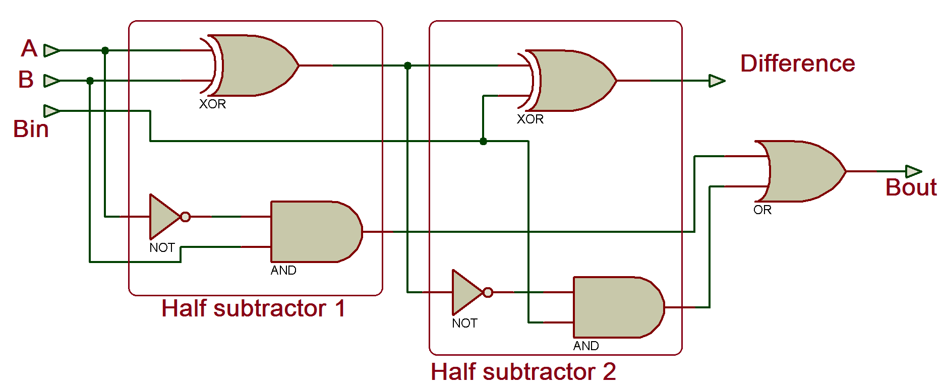
VHDL Tutorial – 11: Designing half and full-subtractor circuits
Solved For the following circuit: 1- drive the state table | Chegg.com
Hybrid input encoded full adder block (SSSC_HIE_NRL adder). | Download ...
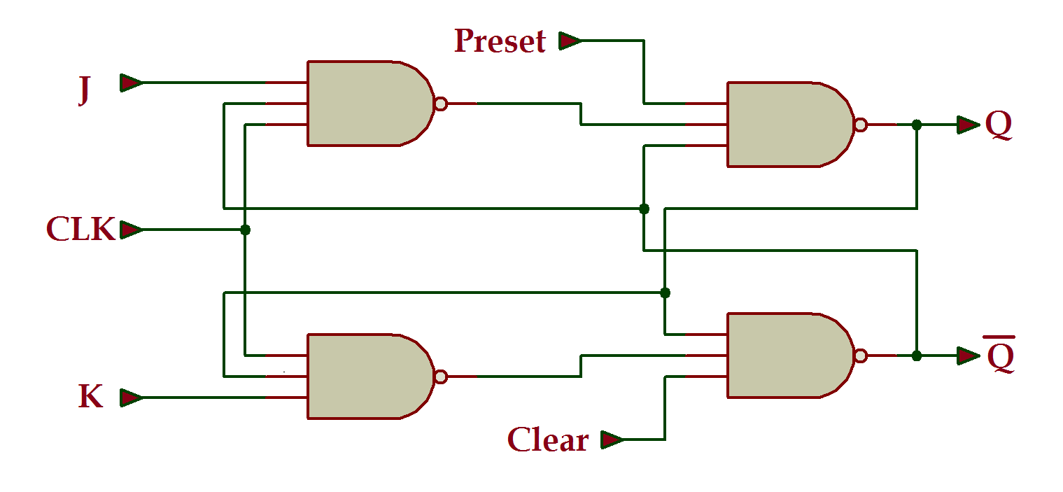
VHDL Tutorial 17: Design a JK flip-flop (with preset and clear) using VHDL
Nonoverlapping clocks: (a) clock signals and (b) possible circuit ...
4 Bit Comparator Circuit Diagram
A circuit board from the Saturn V rocket, reverse-engineered and explained
Internal Scan Chain - Structured techniques in DFT (VLSI)
Digital Logic: digital logic
Ring Counter Digital Works - Electrical Engineering Stack Exchange
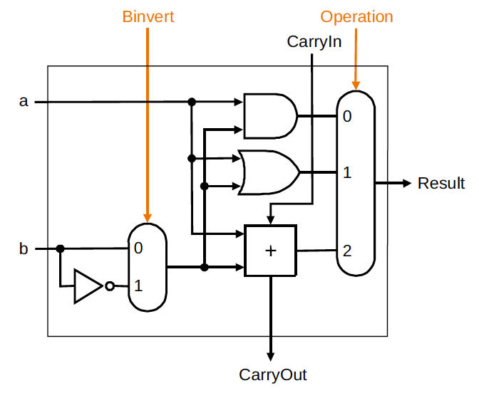
One-Bit ALU
Ken Shirriff's blog
Case Study Comparator Schematic | Download Scientific Diagram
Clock Tree Guidances for better Clock Tree Synthesis - Technology@Tdzire
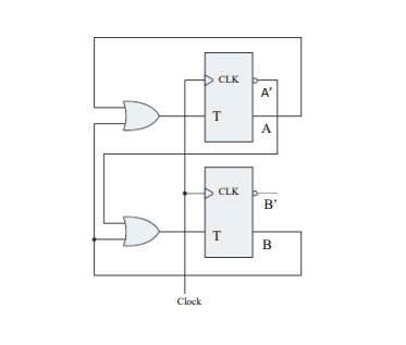
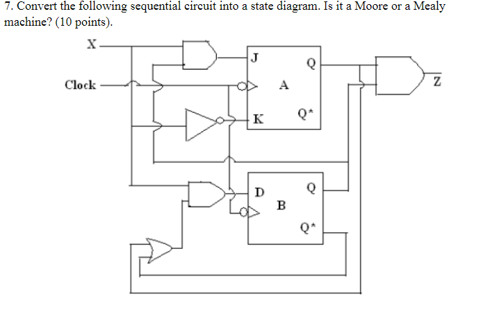
Solved 7. Convert the following sequential circuit into a | Chegg.com
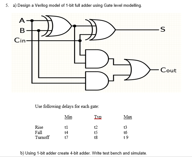
Solved 5. a) Design a Verilog model of 1-bit full adder | Chegg.com
Conventional 1-bit Full Adder | Download Scientific Diagram
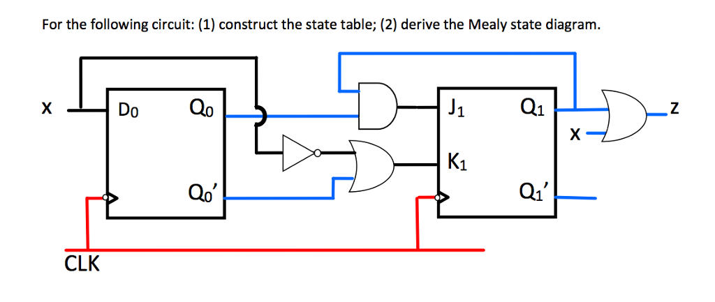
Solved For the following circuit: (1) construct the state | Chegg.com
Solved Identify the function of the circuit schematic shown | Chegg.com
Solved A Combinational Circuit consists of logic gates whose | Chegg.com
Creating an adder with logic gates - by Martin McBride
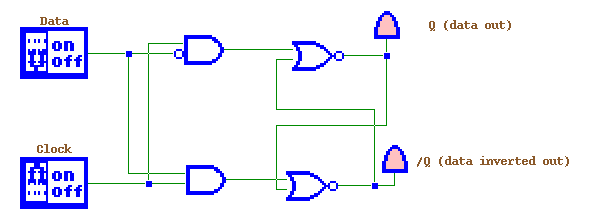
sr flip flop ladder diagram - Wiring Diagram and Schematics
Diagram of control logic of 3-stage CCP gain-stage. | Download ...
STTL AND gate for FPGA implementation [27] | Download Scientific Diagram
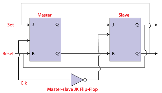
Master-Slave JK Flip Flop in Digital Electronics - Javatpoint
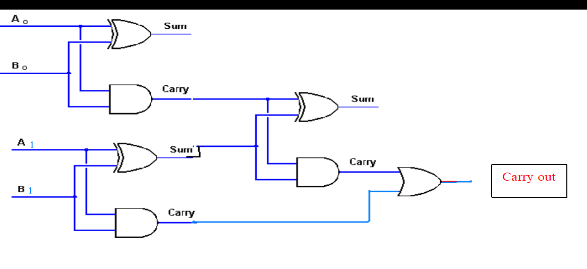
Half Adder and Full Adder using Hierarchical Designing in Verilog ...
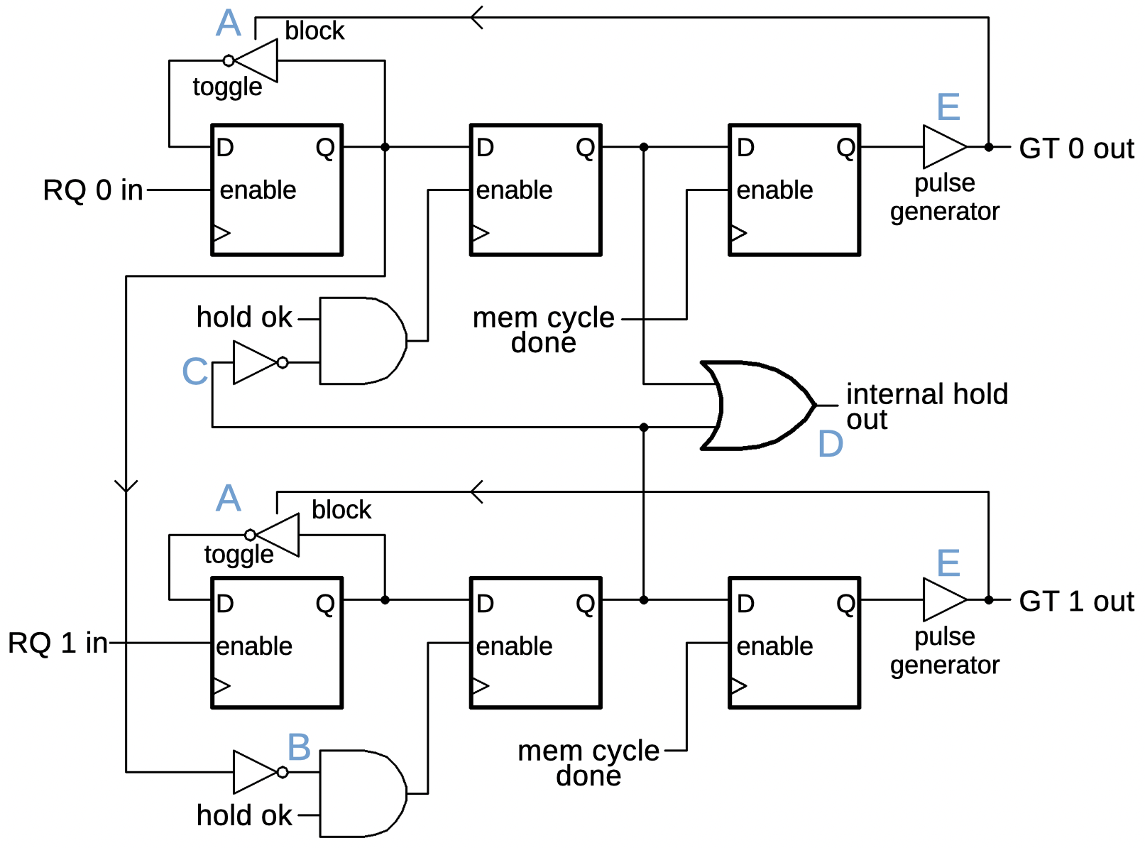
Figure 1 from Data-Loop-Free Self-Timed Circuit Verification | Semantic ...


![STTL AND gate for FPGA implementation [27] | Download Scientific Diagram](https://www.researchgate.net/publication/303916075/figure/fig3/AS:963415434612769@1606707547534/STTL-AND-gate-for-FPGA-implementation-27.gif)