Please enter url.
Login
Logout
Please enter url.
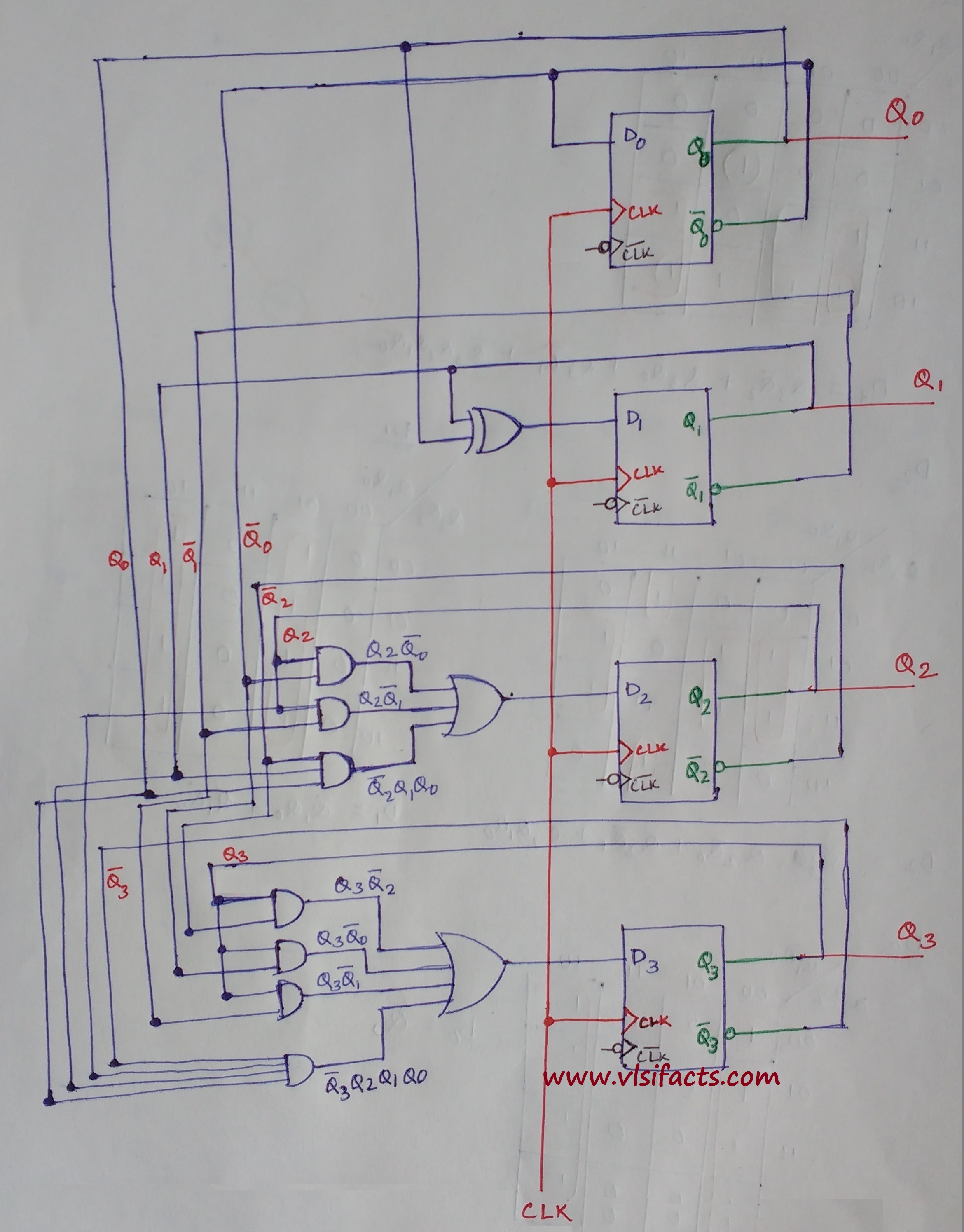
4 Bit Binary Counter Circuit Diagram
tumbo7tschematic.z19.web.core.windows.net
source
Comments
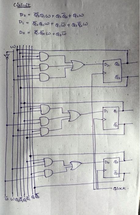
Circuit Design of a 4-bit Binary Counter Using D Flip-flops – VLSIFacts
Design the Moore state diagram, state table, karnaugh map, and circuit ...
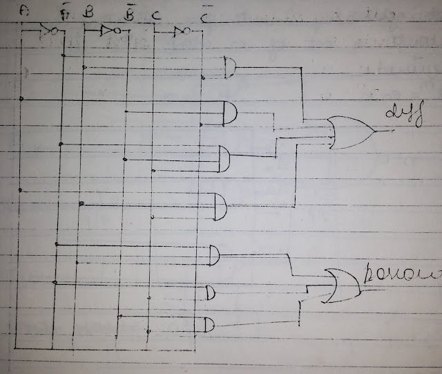
Logic Circuit Diagram Of Full Subtractor
Digital Logic: Number of decoders
Basic Digital Techniques & Applications - PART 5 | माझे चॅनेल
How To Design To 32 Decoders Using To Decoders Quora, 41% OFF
11+ Toyota Prius Trouble Codes Pdf - BlairMikolaj
[Solved] Design a logic circuit to produce a high output only if the ...
Using logisim to create a 4bit controlled comparator ECFICATIONS NPUTS ...
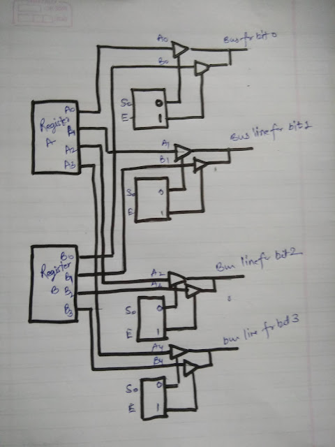
Bus system construction using tri-state buffer - Tutorials
[Solved] Design a 4-bit "universal shift register" using four ...
Solved Design a synchronous counter, which counts in the | Chegg.com
[Solved] [5] Design a digital circuit that performs the four logic ...
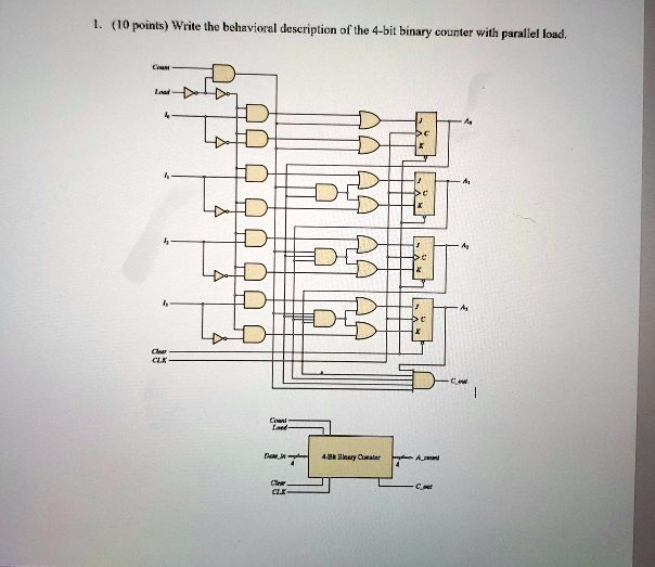
SOLVED: Write the behavioral description of the 4-bit binary counter ...
Given the 3 lines to imes 7413s decoder IC s in Sgre 2 74138 YS Y4 P Y3 ...
4-bit binary counter using J-K flip flops V. SIMULATION OF THE CIRCUIT ...
Solved PLEASE USE TINKER CARD AND MAKE A REPORT Task 1. In | Chegg.com
Solved Please show how this circuit would look in a | Chegg.com
Consider the parity generator (even parity) shown in the truth table ...
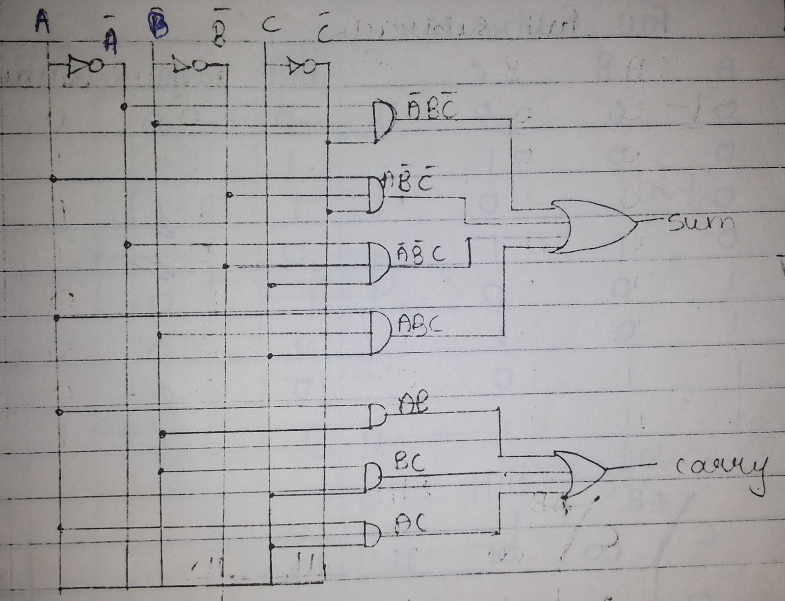
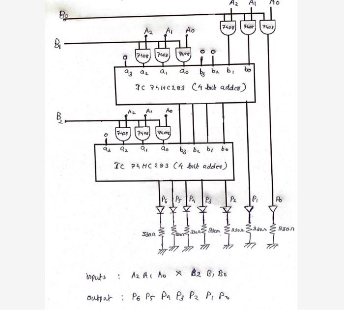
Indie Electronics: My 4 Bit Ripple Carry Adder/Subtractor Project
[Solved] (Design of a Modulo-12 Counter) Design a 4-bit modulo-12 up ...
4 Bit Multiplier Circuit Diagram - Wiring Work
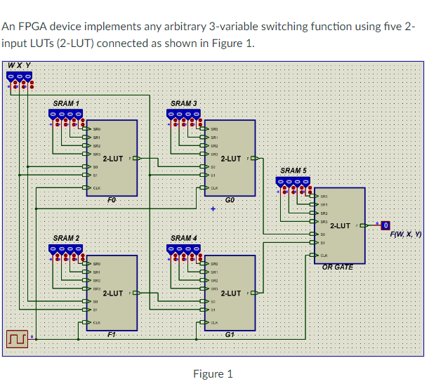
fpga - How to implement a three-input LUT if I have a lot of two-input ...
1. Using only half adders, design a four-bit incrementer circuit (a ...
[Solved] Sketch the circuit schematic for the an 8 bit ring counter ...
Draw a logical diagram of the 4-bit register with mode selection inputs ...
[Solved] please dont skip steps and explain your steps please. neat and ...
Q. 4.22: Design an excess-3-to-binary decoder using the unused ...
Solved Write the behavioral description of the 4-bit binary | Chegg.com
Solved 1. Implement and simulate the traffic lights circuit | Chegg.com
[Solved] (1) Below are the FFs excitation equations of a synchronous ...
How to design a combinational circuit that will compare two 8-bit ...
[DIAGRAM] Circuit Diagram For 7 Segment Decoder - MYDIAGRAM.ONLINE
BCD to 7 segment Display Decoder - YouSpice
An FPGA device implements any arbitrary 3-variable | Chegg.com
4-Bit-D-Flip-Flop
Counter-Flip-Flop
D-Flip-Flop-Up-Counter
Counter-Using-D-Flip-Flop
Jk-Flip-Flop-Up-Counter
3-Bit-Counter-D-Flip-Flop
Ring-Counter-Using-D-Flip-Flop
4-Bit-Up/Down-Counter-Using-D-Flip-Flop
2-Bit-Counter-Jk-Flip-Flop
Synchronous-Counter-D-Flip-Flop
Binary-Counter-D-Flip-Flop
4-Bit-Counter-Circuit
4-Bit-Counter-State-Diagram
Jk-Flip-Flop-Ripple-Counter
D-Flip-Flop-Asynchronous-Counter
4-Bit-D-Flip-Flop-Register


![[Solved] Sketch the circuit schematic for the an 8 bit ring counter ...](https://mavink.com/images/loadingwhitetransparent.gif)


![[DIAGRAM] Circuit Diagram For 7 Segment Decoder - MYDIAGRAM.ONLINE](https://www.electricaltechnology.org/wp-content/uploads/2018/05/schematic-of-BCD-to-7-Segment-Decoder.png)