Please enter url.
Login
Logout
Please enter url.
Bode Diagram Phase Plot Rc Circuit
manualpartjacob.z21.web.core.windows.net
source
Comments
RC circuits and Bode plots - YouTube
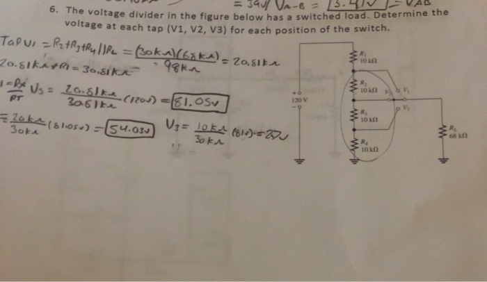
Solved B.Q =34 VA- 6. The voltage divider in the figure | Chegg.com
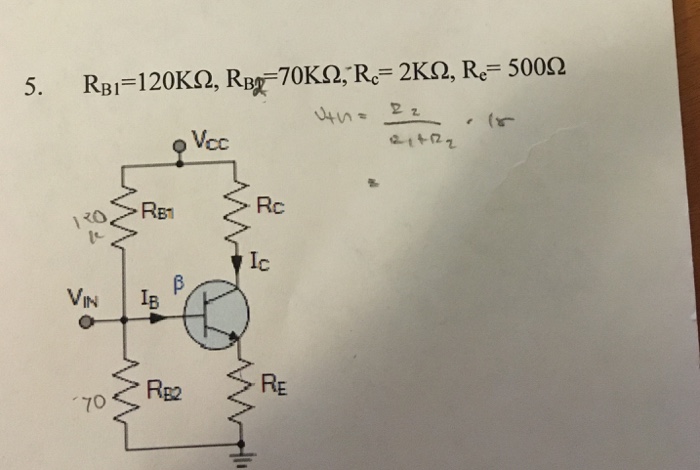
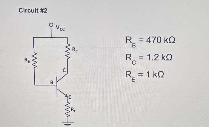
Solved Vcc=15v and beta = 120. Determine mode of operation, | Chegg.com
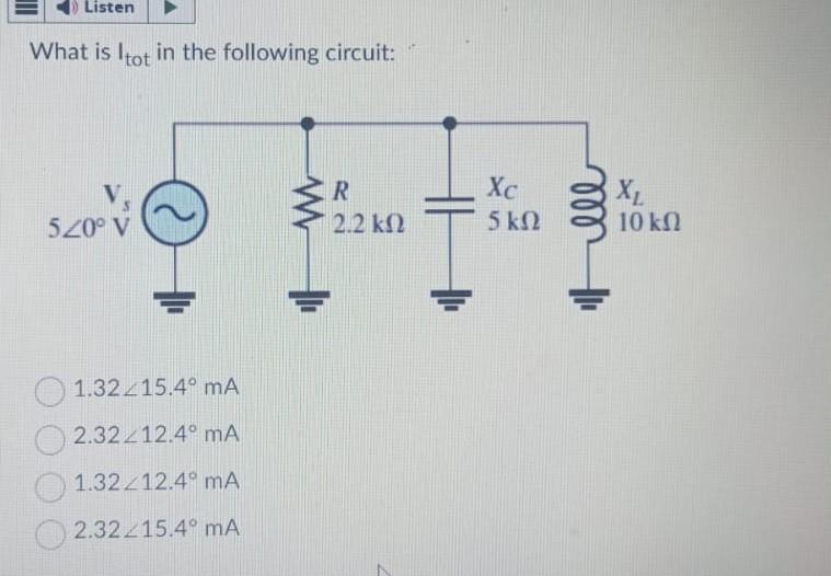
Solved What is Itot in the following | Chegg.com
Solved anyone can solve it step by step. use:current or | Chegg.com
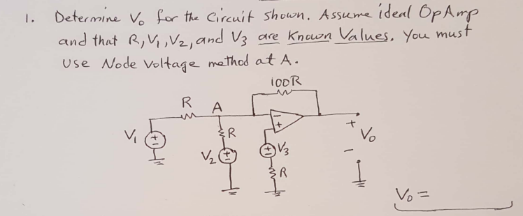
Solved 1. Determine vo for the circuit shown. Assume ideal | Chegg.com
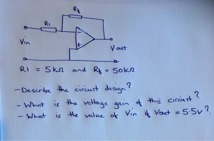
Solved R1=5kΩ and Rf=50kΩ -Describe the circuit design? - | Chegg.com
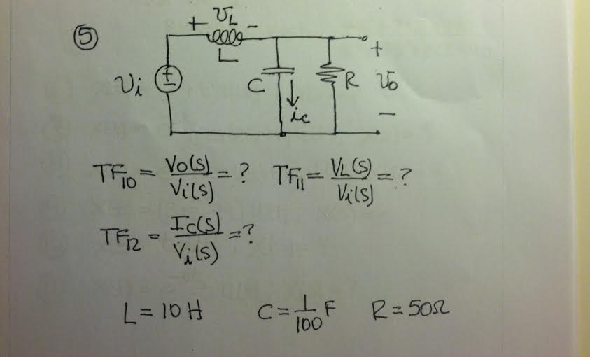
Solved: Find The Transfer Functions.TF10 = Vo(s)/Vi(s) = ?... | Chegg.com
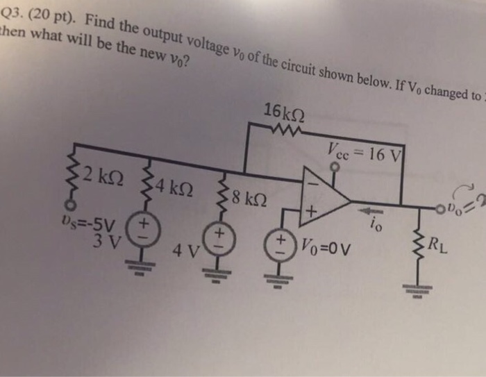
Solved Find the output voltage v0 of the circuit shown below | Chegg.com
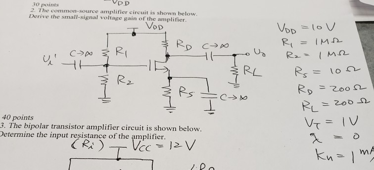
Solved VDD 30 points 2. The common-source amplifier circuit | Chegg.com
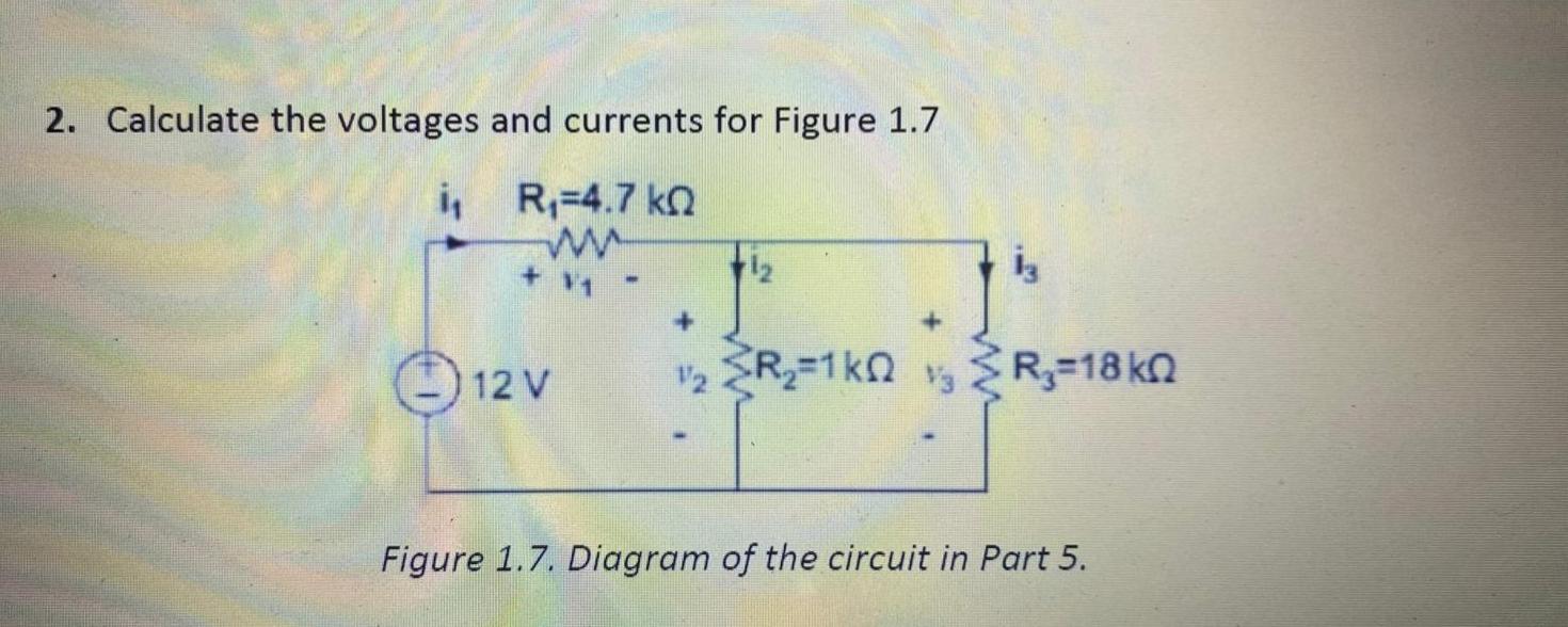
Solved 2. Calculate the voltages and currents for Figure 1.7 | Chegg.com
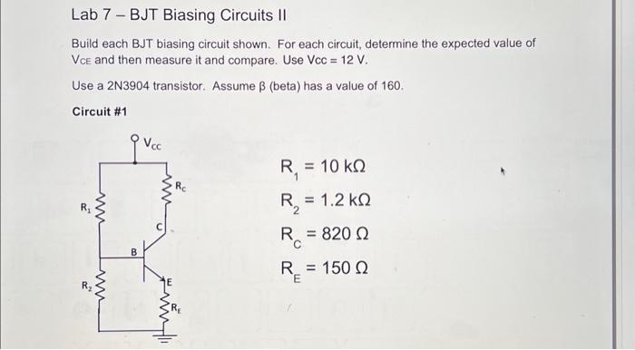
Solved Lab 7 - BJT Biasing Circuits II Build each BJT | Chegg.com
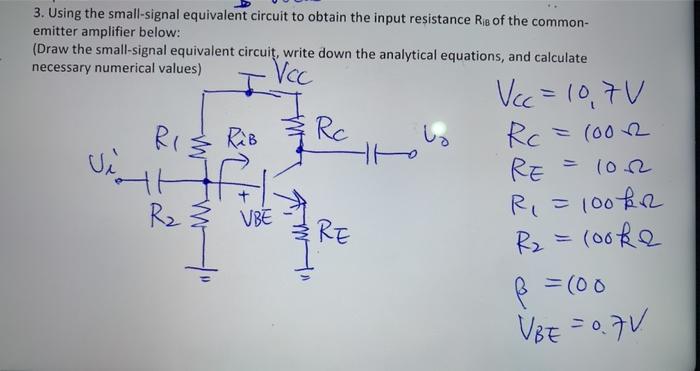
Solved 3. Using the small-signal equivalent circuit to | Chegg.com
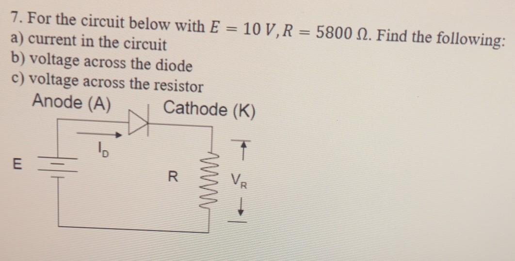
Solved 7. For the circuit below with E = 10 V, R = 5800 N. | Chegg.com
Solved Build each BJT biasing circuit shown. For each | Chegg.com
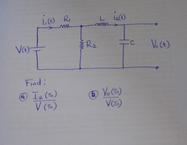
Solved Find the transfer function of (a) and (b) using the | Chegg.com
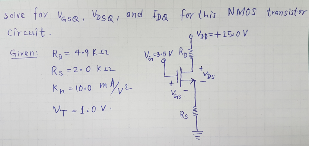
Solved Note: Microelectronic circuits, MOSFETs Transistors. | Chegg.com
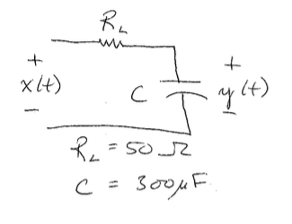
Solved C (t) l4) | Chegg.com
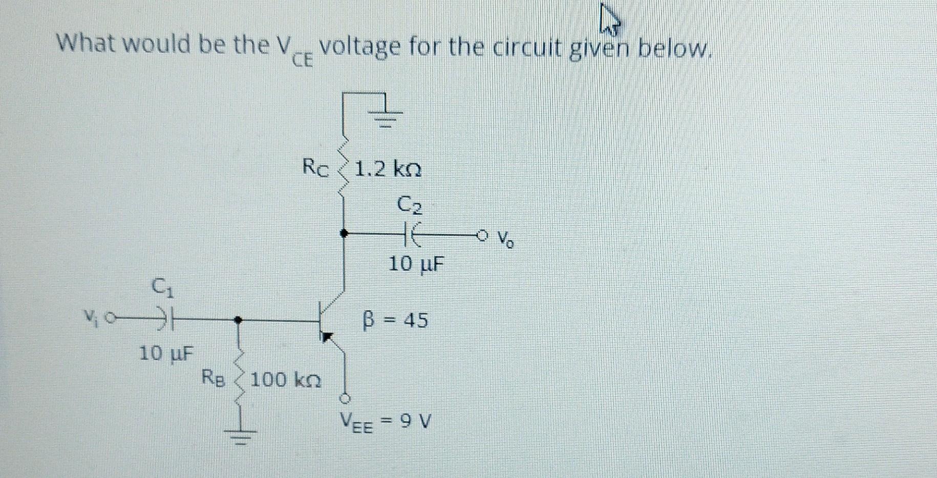
Solved What would be the VCE voltage for the circuit given | Chegg.com
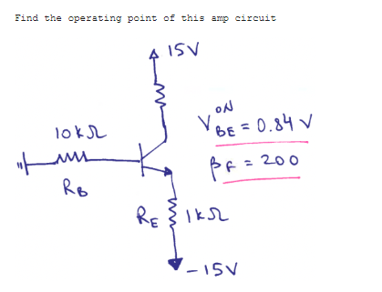
Find the operating point of this amp circuitQuestion | Chegg.com
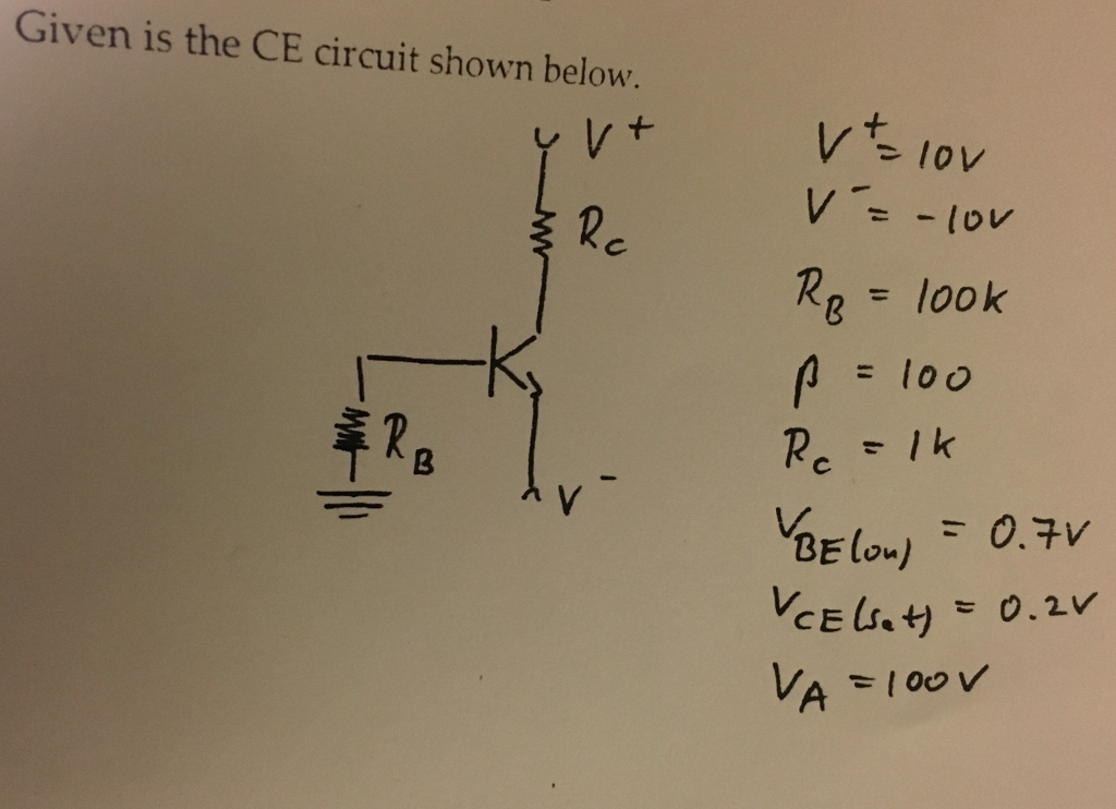
Solved 1- Determine IBQ , VCEQ and ICQ ? 2- Why the | Chegg.com
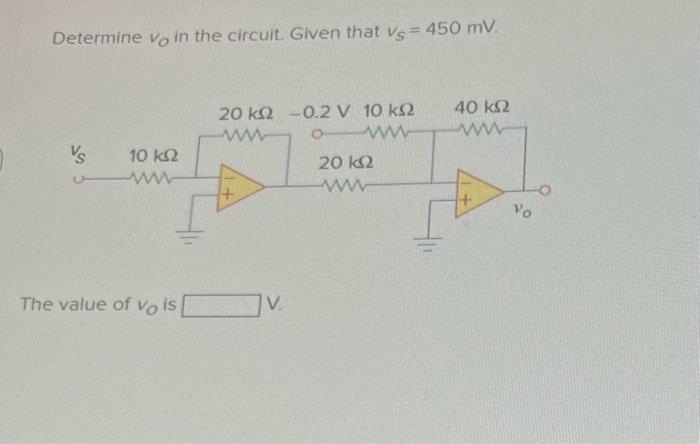
Solved Determine vO in the circuit. Given that vs=450mV. The | Chegg.com
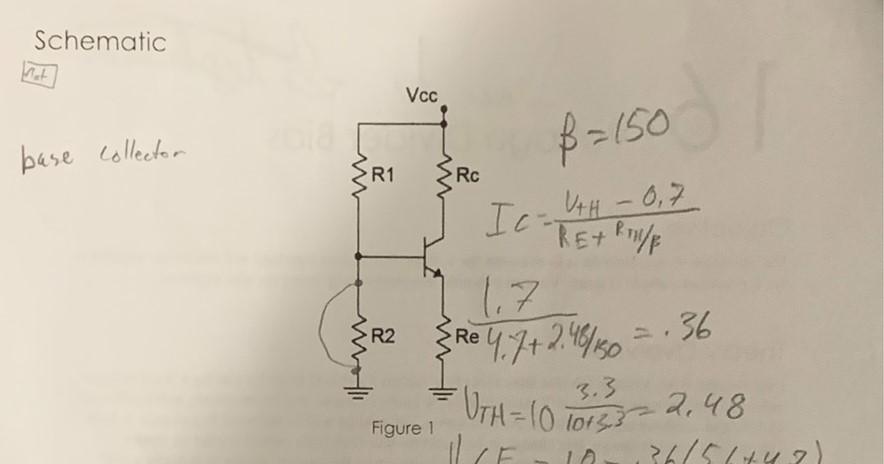
Solved Schematic Wat Vcc 8=150 base collector R1 Rc | Chegg.com
Solved Draw the DC and Ac load lines for the amplifier with | Chegg.com
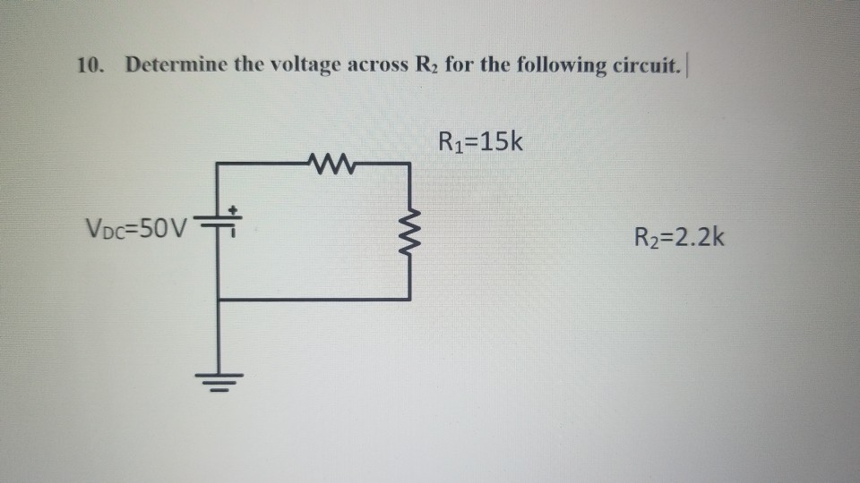
Solved 10. Determine the voltage across R2 for the following | Chegg.com
Solved 2. Draw the small-signal equivalent circuit and | Chegg.com
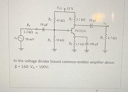
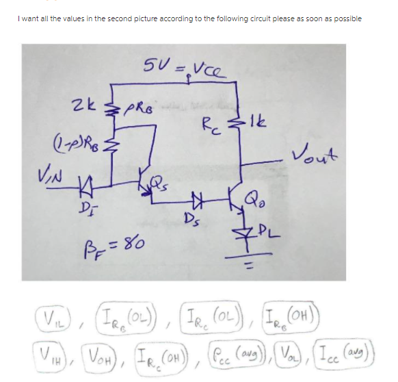
Solved I want all the values in the second picture according | Chegg.com
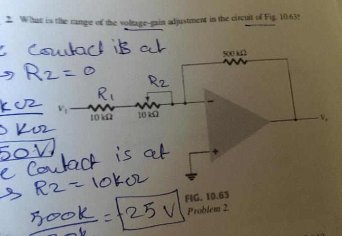
Solved 2. What is the range of the voltage-gain adjustment | Chegg.com
Active Filters | Audio crossover, Filters, Active
Solved: For Circuit In Fig 1 Use The Nodal Analysis To Cal... | Chegg.com
Solved I 35 points 1. The source follower is given below. | Chegg.com
Solved 4) In the clipper circuits shown above assume the | Chegg.com
Solved Voc + 20 V O 10KO 40 ΚΩ 2 kn h 11 Determine ve and to | Chegg.com
Solved Problem Three: The op-amp in the circuit shown is | Chegg.com
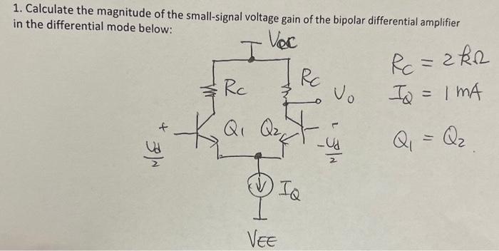
Solved 1. Calculate the magnitude of the small-signal | Chegg.com
Bode-Plot-LRC-Circuit
Low-Pass-Bode-Plot
Bode-Plot-Zero
Bode-Plot-Diagram
Integrator-Bode-Plot
Bode-Plotter
Bode-Plot-Poles-and-Zeros
RC-Bode-Plot
Bode-Plot-Supercapacitor
Bode-Plot-Asymptotes
Bode-Plot-Control-System
RC-Filter-Bode-Plot
Bode-Plot-DC-Motor
Bode-Diagram-of-Transfer-Function
AC-Bode-Plot
Diagramme-De-Bode-Circuit-RC