Please enter url.
Login
Logout
Please enter url.
Pass Transistor Logic - Notes - LearnPick India
learnpick.in
source
Comments
Solar tracking system - Report
[Solved] Assume diodes D1 and D2 are ideal. Find I1, I2 and Vo for the ...
ELECTRONICS SHOW: AKTU NOTES ON CLIPPER CIRCUIT, CLAMPER CIRCUIT AND ...
Unit 5 jntu network analysis notes | PDF
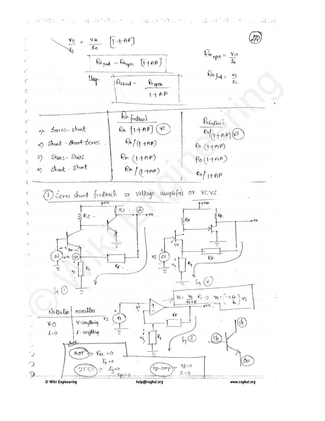
Analog Electronics HandWritten Notes | PDF
block diagram.pdf
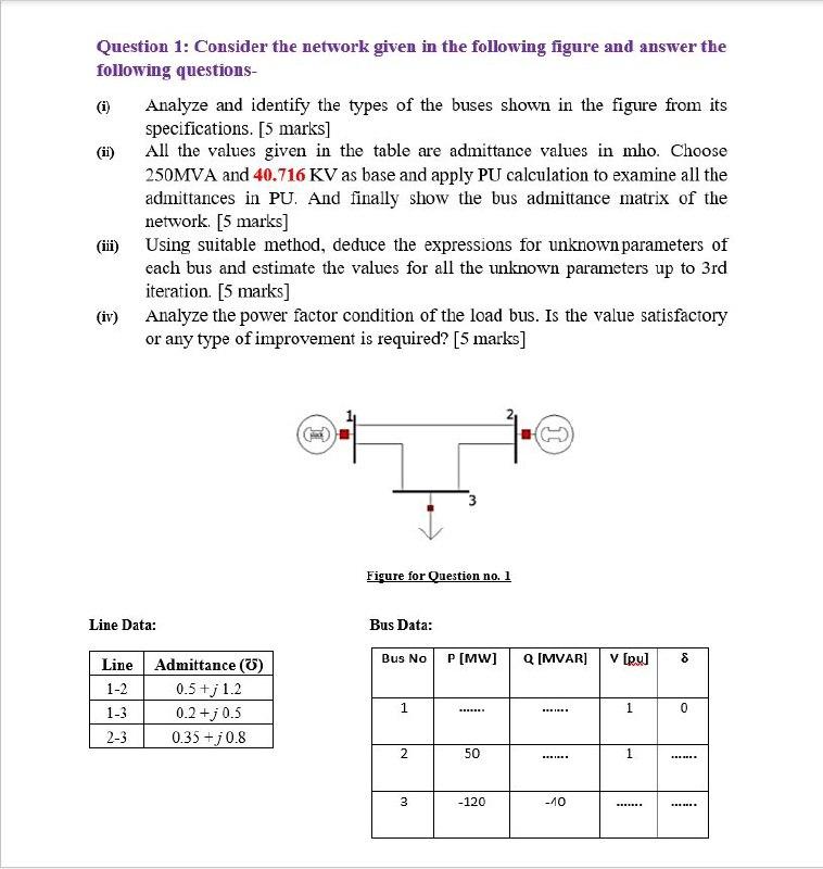
Solved Question 1: Consider the network given in the | Chegg.com
Ee 1351 power system analysis
AP SSC Science Question Paper Solutions 2023 PDF Download
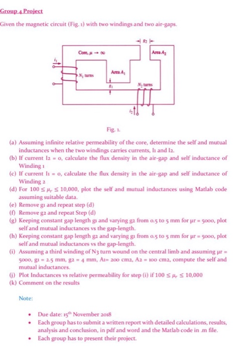
Solved Group &Project Given the magnetic circuit (Fig. 1) | Chegg.com
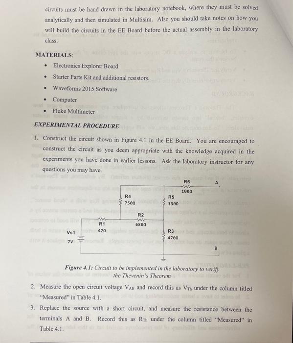
Solved 4. Calculate the voltage across and the current | Chegg.com
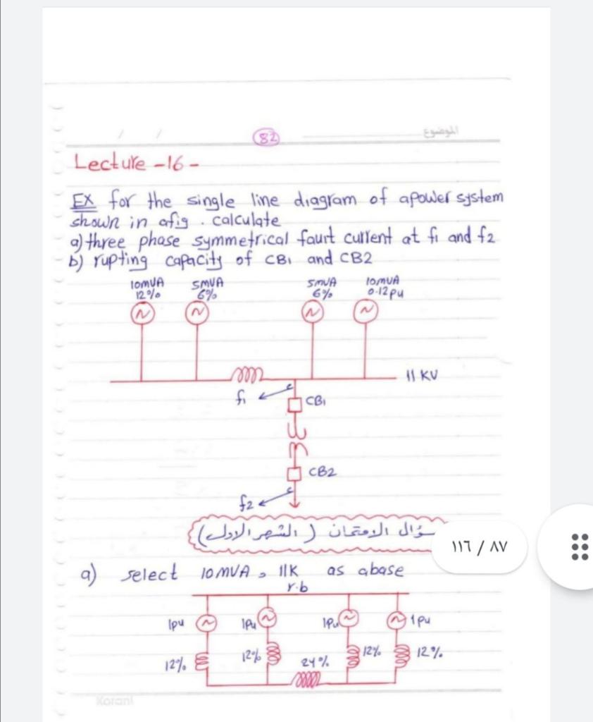
Solved 82 Lecture -16- EX for the single line diagram of | Chegg.com
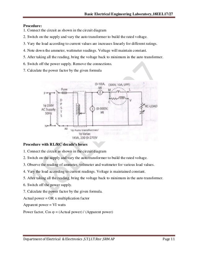
VTU Basic electrical Lab manual | PDF
Answered: Consider the circuit shown in (Figure… | bartleby
SOLUTION: Jfet mosfet analog and digital electronics - Studypool
SOLUTION: Electrical engineering power electronics chopper circuits ...
basic electrical manual 18 scheme
Fundamentals of CMOS VLSI Assignment questions with answers
Digital Logic >>Short Answer
[Solved] . Exercise IX.5: Write the mesh equations for the network ...
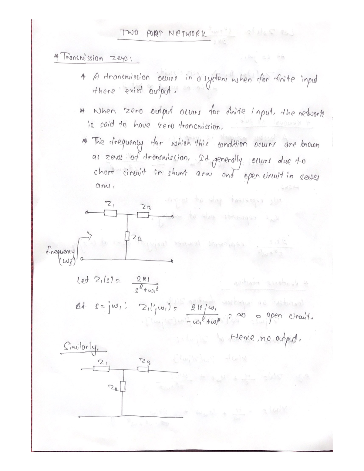
Two Port Network - Filter Design Notes - filter design - TU - Studocu
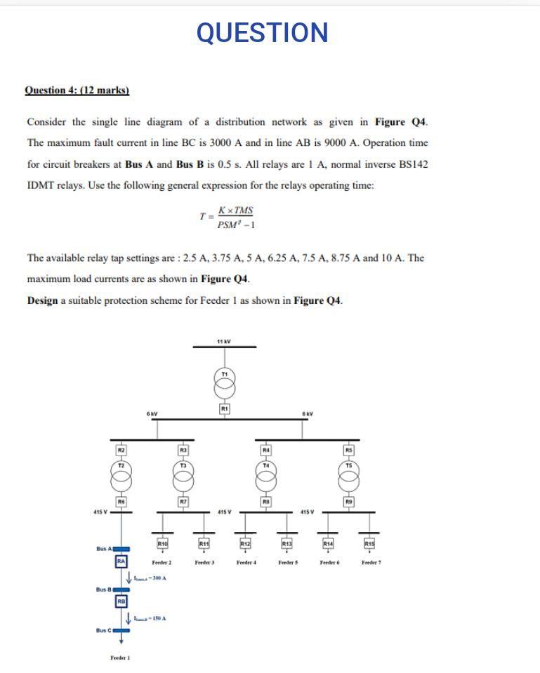
Solved QUESTION Question 4: (12 marks) Consider the single | Chegg.com
Pass Transistor Logic - Notes - LearnPick India
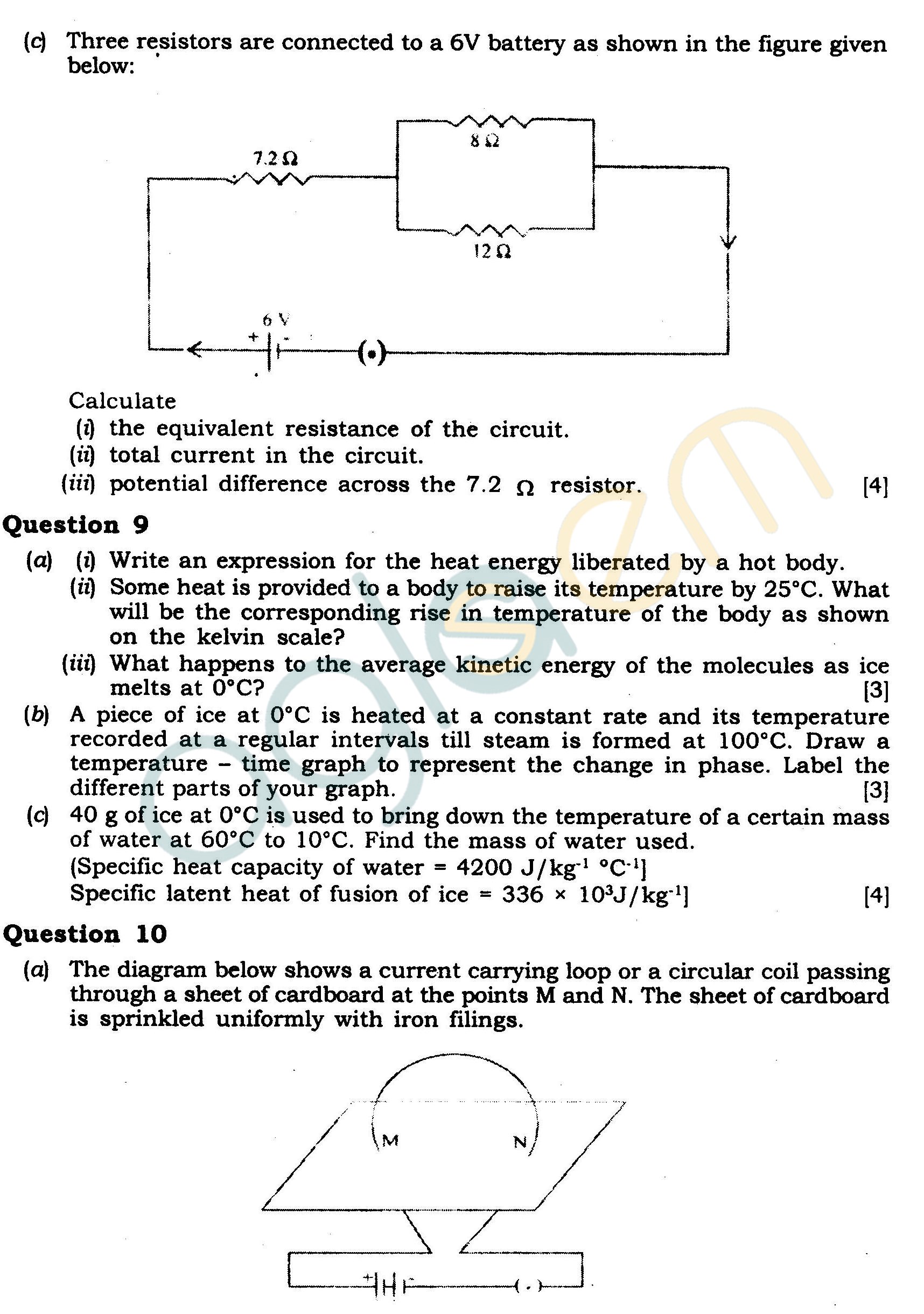
ICSE Class X Exam Question Papers 2012: Physics (Science Paper-1)
SOLUTION: Semiconductor short notes - Studypool
EXP13 PNP Transistor As An Amplifier | PDF | Bipolar Junction ...
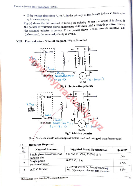
22418 Electric Motors & Transformers Manual Answers
Solved A single line diagram of two bus system shown in | Chegg.com
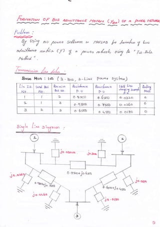
Power Systems Engineering - Formation of Network Matrix Y-bus solution ...
Analog Electronics Notes - Akshansh
Solved 13 Figure 1 1. a) Describe the purpose and the | Chegg.com
Refregeration & Air Conditioning 1 (RAC) Mechanical Engineering ...
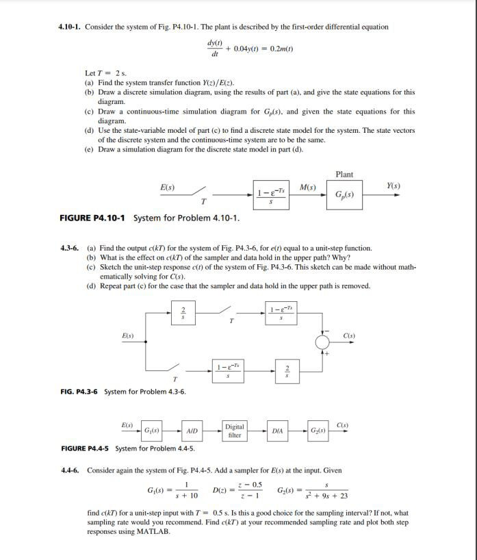
Solved 4.10-1. Consider the system of Fig. P4.10-1. The | Chegg.com
Analog Electronics HandWritten Notes | PDF
[Solved] Consider a CMOS process with VDD = 1.8 V, VTN = 0.7 V, VTP = 0 ...


![[Solved] Consider a CMOS process with VDD = 1.8 V, VTN = 0.7 V, VTP = 0 ...](https://mavink.com/images/loadingwhitetransparent.gif)