Please enter url.
Login
Logout
Please enter url.
Surface Roughness of Engineering Drawing - Guru Teknik Mesin
omesin.com
source
Comments
Surface Roughness of Engineering Drawing - Guru Teknik Mesin
Surface Roughness of Engineering Drawing - Guru Teknik Mesin
Surface Roughness of Engineering Drawing - Guru Teknik Mesin
Surface Finish - Roughness - Symbols, Charts, Callouts & Costs
Machining conditions of a rotational part | Download Scientific Diagram
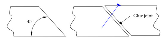
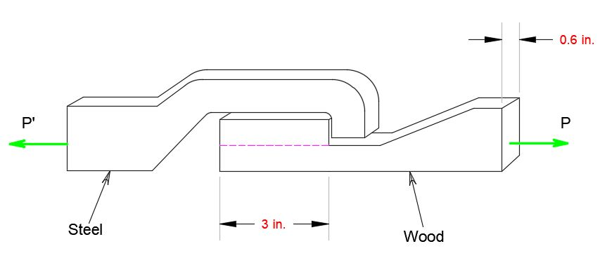
When the force P reached 8 kN, the wooden specimen shown failed in ...
Mechanical Technology: Types of Welds
Mechanics of Materials - 9780073398235 - Exercise 17 | Quizlet
The wear schematic diagram of shaft sleeve. | Download Scientific Diagram
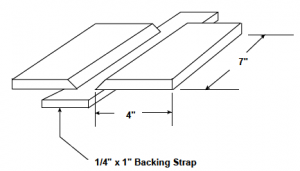
Manufacturing process of press-break sections [3] | Download Scientific ...
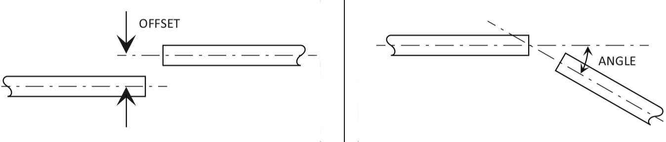
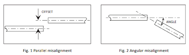
Gearbox Misalignment: Signs and Causes - Motion Control Tips
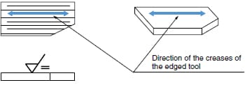
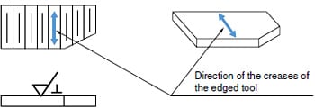
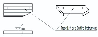
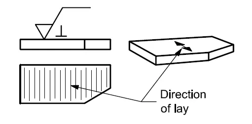
Understanding Surface Roughness Symbols | Introduction To Roughness ...
Edge of the weld bead. | Download Scientific Diagram
Schematic diagram of crack propagation in orthogonal cutting | Download ...
Parallel milling second variant. | Download Scientific Diagram
The geometry and coordinate system of a mismatched microstrip ...
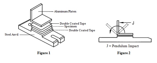
Internal Bond Strength Tester - Laboratory Testing Instrument @ Malaysia
Schematic of measuring the quality characteristics such as Ra and Kt ...
Effect of strain rate on the notch-bend strength at temperature T ...
Sketch of the loading configurations for (a) shaft-loaded blister, (b ...
Figure 1 from OPTIMIZATION OF KERF AND SURFACE ROUGHNESS OF AL 7 475-T ...
Surface roughness pictorial representation method | Solving the ...
Tips for Passing the AWS 3G FCAW Certification | WELDING ANSWERS
Filling flow and the melt and mold temperature on the interface. Mushy ...
13: Single microstrip wire | Download Scientific Diagram
Understanding Surface Roughness Symbols | Introduction To Roughness ...
The location of the points in which the temperature is measured ...
Materials | Free Full-Text | Possibility to Use Short Sawn Timber in ...
Gearbox Misalignment: Signs and Causes - Motion Control Tips
2. Schematic of LIF set up showing the junction plane, camera (not ...
The basices of fits - THE INVENTIVE
a Cutting forces in orthogonal metal cutting applied by cutting tool ...
SHAFT ALIGNMENT - RIM AND FACE METHOD
Waveguide combiner (a ¼ 18.85, b ¼ 4.75, b 1 ¼ b 2 ¼ 5.2, dist ¼ 3.4, r ...
a) Mounting position of the vibration sensor, b) Measure of flank wear ...


![Manufacturing process of press-break sections [3] | Download Scientific ...](https://www.researchgate.net/publication/354862674/figure/fig5/AS:1072657189572610@1632752811450/6-Manufacturing-process-of-press-break-sections-3.png)