Please enter url.
Login
Logout
Please enter url.
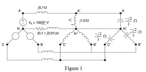
[Solved] Assume that supply voltage is of the form... | Course Hero
coursehero.com
source
Comments
Ground fault protection on ungrounded and high resistance grounded systems
Choosing the Best Three-phase Power Measurement Method - Technical Articles
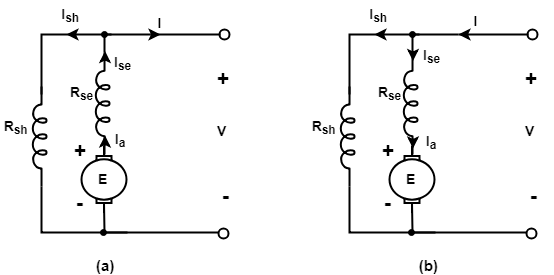
Types of DC Generators | Electrical4u
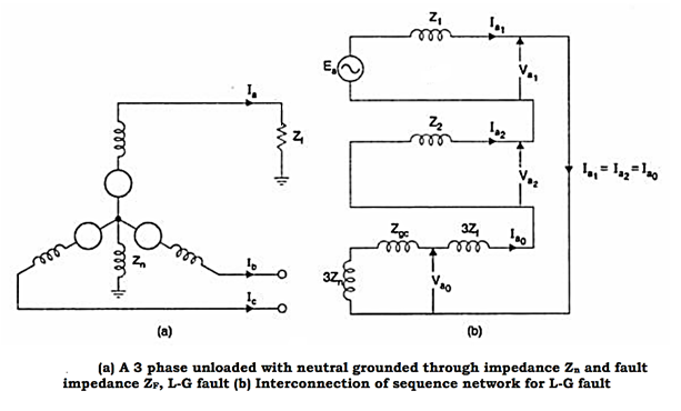
notes - engineering - sem-1 - power system protection - unit 2 faults ...
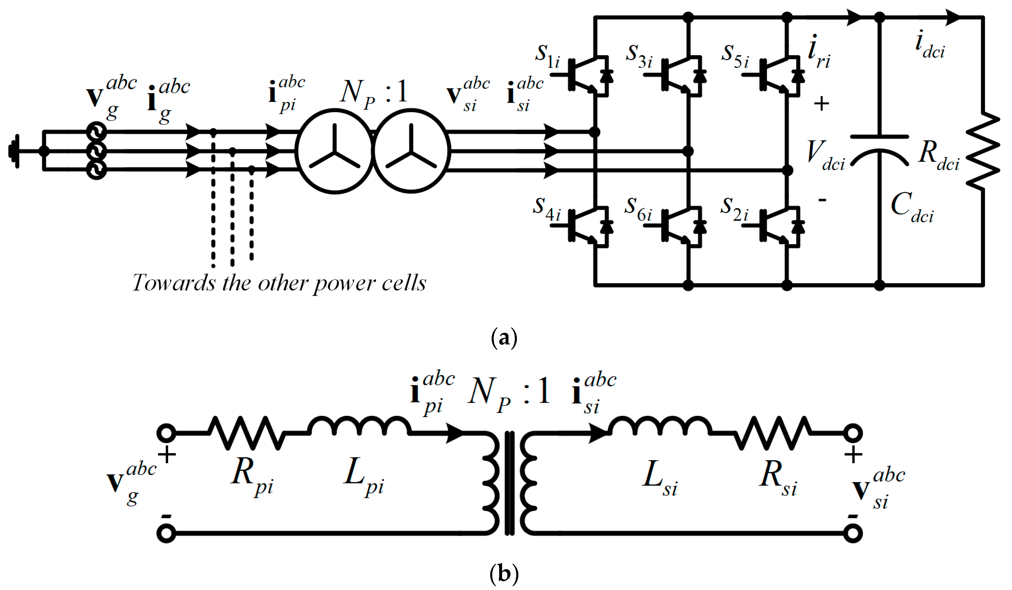
Figure 1 from Determination of Per-Phase Equivalent Circuit Parameters ...
Equivalent Circuit of Induction Motor that will be modified | Download ...
Figure 1 from Single-Phase Transformer Harmonics Produced During ...
Lumped-circuit model for mutual coupling between track circuit, power ...
Consider the balanced three-phase system shown in Figure 2.34. Deter ...
Induction motor equivalent circuit a) qs Circuit and b) ds Circuit ...
Schematic diagram of the equivalent test system. | Download Scientific ...
CHAPTER 4 THREE-PHASE POWER - LEKULE
Capacitor voltage balancing of a three‐phase neutral‐point clamped bi ...
Ground Fault Protection on Ungrounded and High-Resistance Grounded ...
Restricted Earth Fault Theory - The Earth Images Revimage.Org
Circuit Symbol Magnetising Coil In Electric Motorcycle - Circuit Diagram
What Every Engineer Should Know About Electrical Grounding - element14 ...
[PDF] Magnetic Flux Compression Generators : a Tutorial and Survey ...
Parallel hybrid filter configuration. | Download Scientific Diagram
Figure 6 from Design and Implementation of a STATCOM Based on a ...
Energies | Free Full-Text | Finite Control Set—Model Predictive Control ...
Voltage Profile of Transmission Line - EEEGUIDE.COM
Equivalent circuit of faulted bus segment with probe power unit ...
Types of D.C Machine - javatpoint
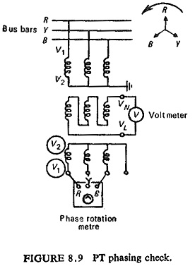
Potential Transformer Tests | Features and Design of Fault Investigation
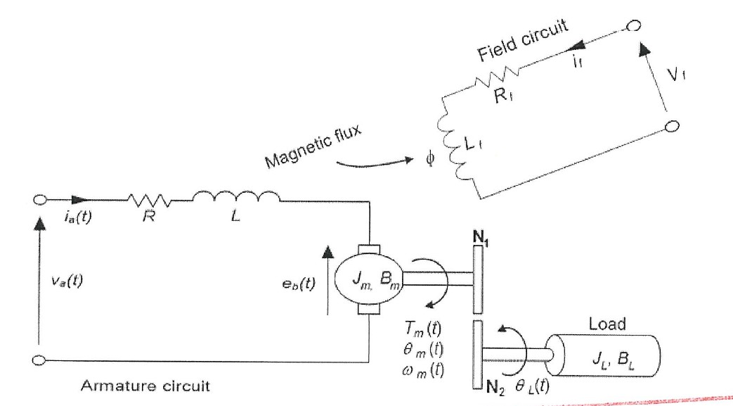
Solved (b) The schematic diagram of a DC motor with gear is | Chegg.com
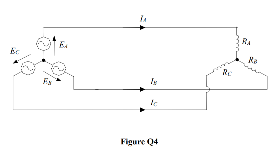
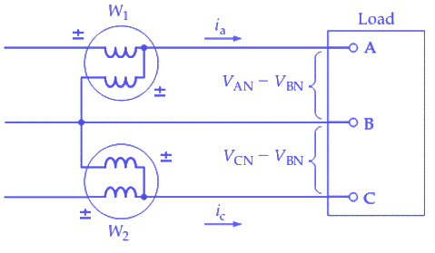
Solved A three-phase, three-wire ABC sequence system with an | Chegg.com
Circuit configuration of Q-mode. | Download Scientific Diagram
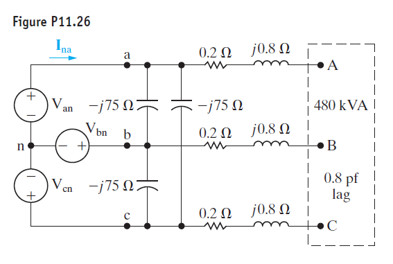
Solved The line-to-neutral voltage at the terminals of the | Chegg.com
Current transformer (a) Connection diagram, (b) Equivalent diagram ...
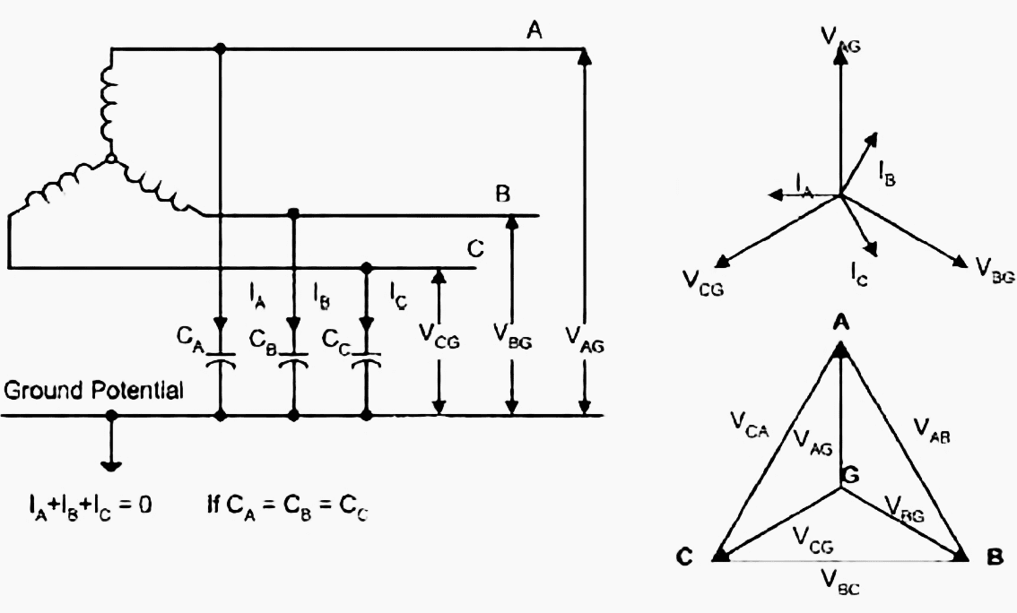
shows the disturbance for C phase to ground. Therefore, the neutral is ...
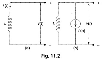
Application of LCR Circuit
Pulse-transformer-based gate drive employed in the proposed ...
Engineering Photos,Videos and Articels (Engineering Search Engine ...
Circuit diagram of parallel operation test of single phase transformer ...


![[PDF] Magnetic Flux Compression Generators : a Tutorial and Survey ...](https://d3i71xaburhd42.cloudfront.net/f20b94c86b9620166bdb82556b5be93261c80c64/25-Figure19-1.png)