Please enter url.
Login
Logout
Please enter url.
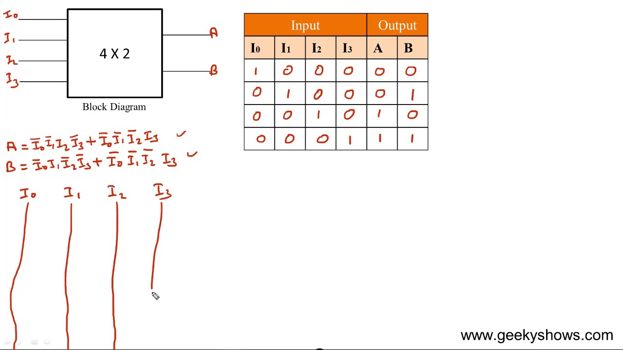
Encoder Circuit Diagram And Truth Table
wiringpartaubrey.z6.web.core.windows.net
source
Comments
Design 4 x 2 Encoder (Hindi) - YouTube
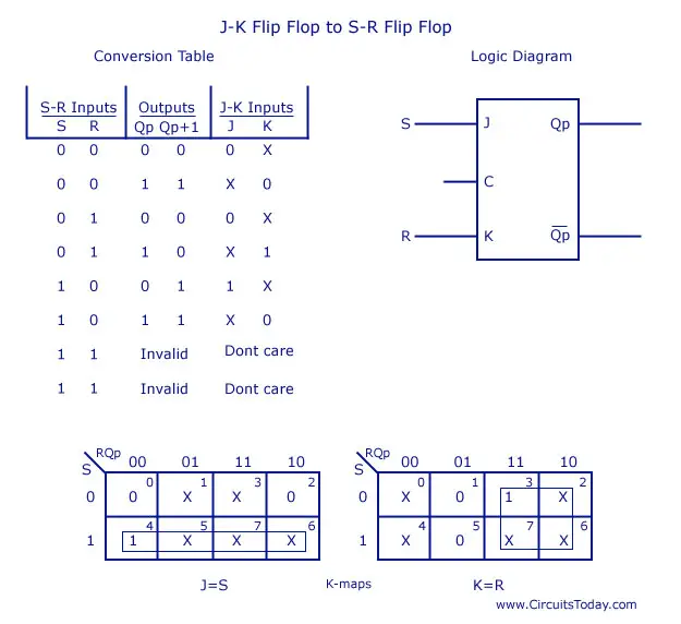
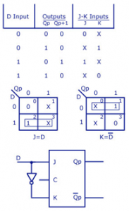
Flip Flop Conversion-SR to JK,JK to SR, SR to D,D to SR,JK to T,JK to D
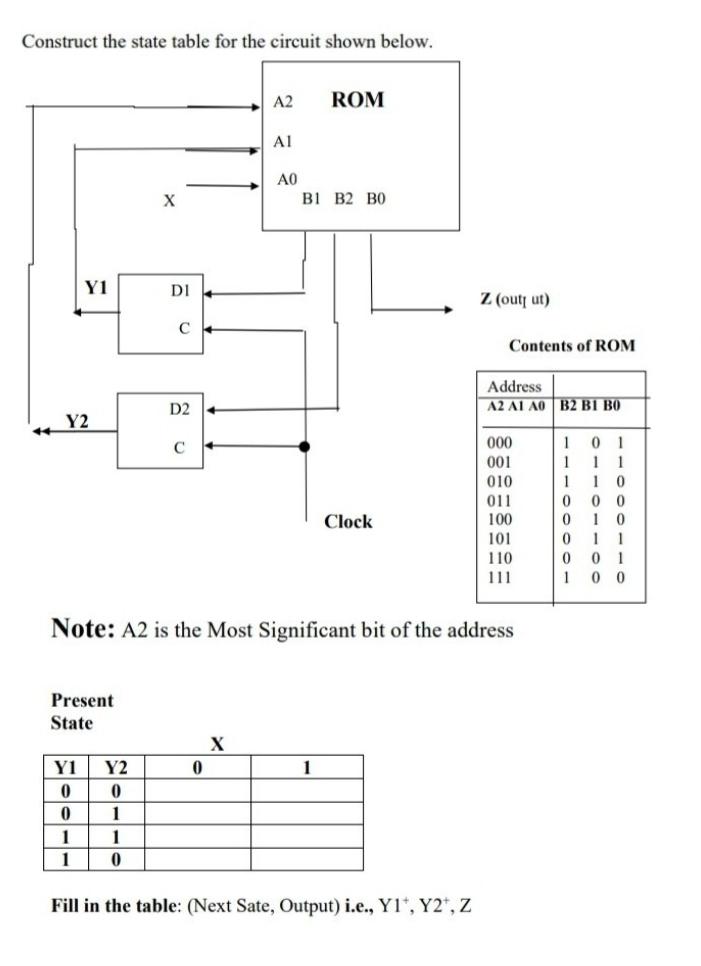
Solved Construct the state table for the circuit shown | Chegg.com
Digital Electronics Section 7 - Electronics and Communication ...
Race Around Condition - Digital Logic - Computer Science Engineering ...
Computer Science Archive | April 08, 2016 | Chegg.com
VHDL || Electronics Tutorial
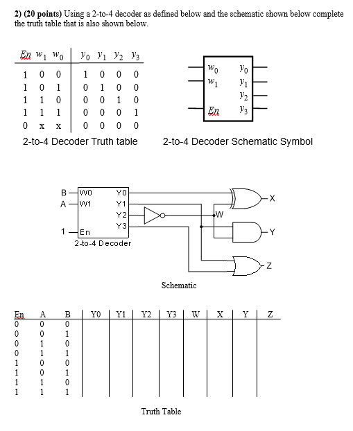
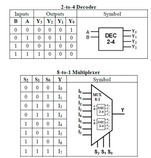
(Get Answer) - Build one 8X1 MUX using two 2X4 decoders. The truth ...
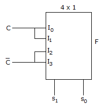
Verilog code for 4X1 MUX using UDP
Implementing Logic Using 2x4 Decoder (Confusions with Non/Negated ...
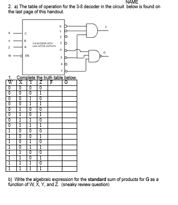
Solved I. The 2-4 decoder in the circuit below is identical | Chegg.com
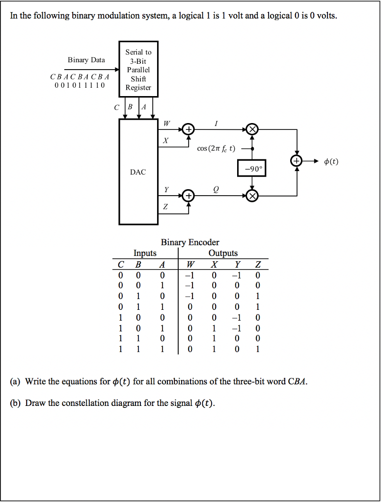
Solved In the following binary modulation system, a logical | Chegg.com
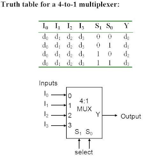
A Comprehensive Guide to 2:1, 4:1, 8:1, and 16:1 Multiplexers | by ...
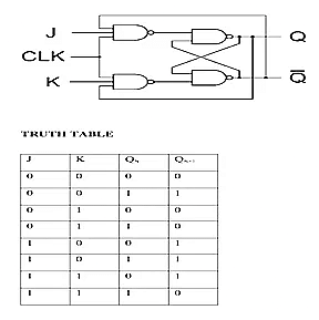
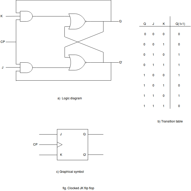
JK Flip-Flop | Computer Organization and Architecture Tutorial - javatpoint
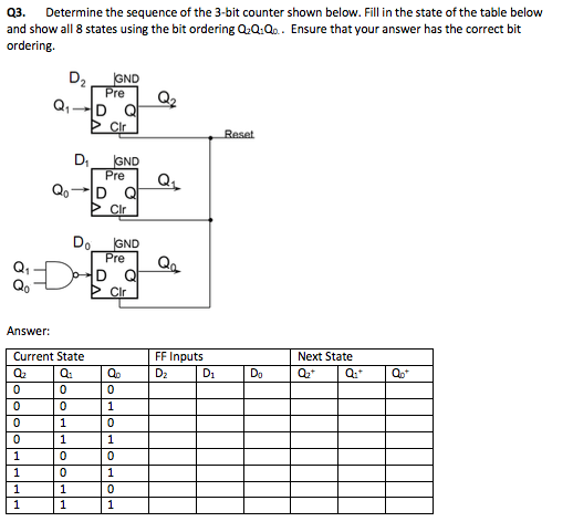
Solved Q3. Determine the sequence of the 3-bit counter shown | Chegg.com
EL Gammal Electronices 74123
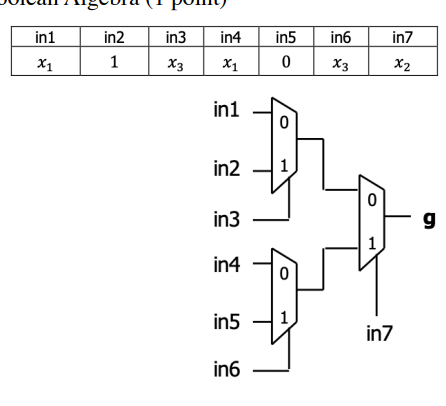
Solved Fill in the truth table below for the boolean | Chegg.com
Raaz San Dee: Flip Flop Conversion
რეკვიზიტები - მიმღები ბანკი "საქართველოს ბანკი", ბანკის კოდი: BAGAGE ...
Please explain on how to get the answer. Thank | Chegg.com
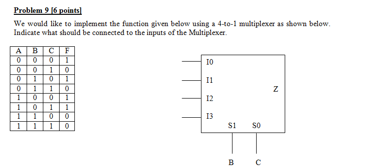
Solved We would like to implement the function given below | Chegg.com
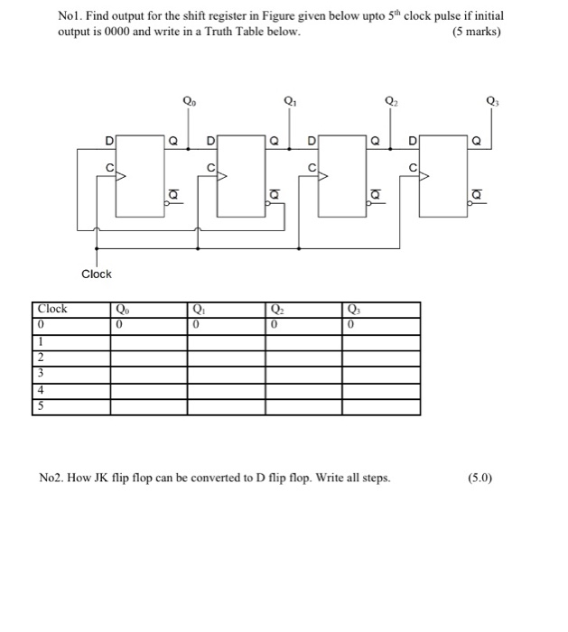
Solved Nol. Find output for the shift register in Figure | Chegg.com
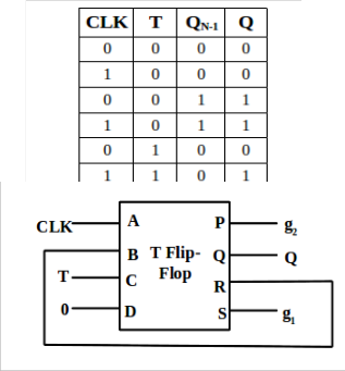
how the output of flip flop is determine by the input (truth table ...
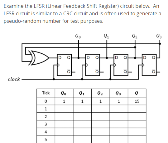
Solved Examine the LFSR (Linear Feedback Shift Register) | Chegg.com
Solved 1. Half-Adder (X+Y) Construct the circuit given in | Chegg.com
Solved As shown, we are using 4:1 and 2:1 mux's to design | Chegg.com
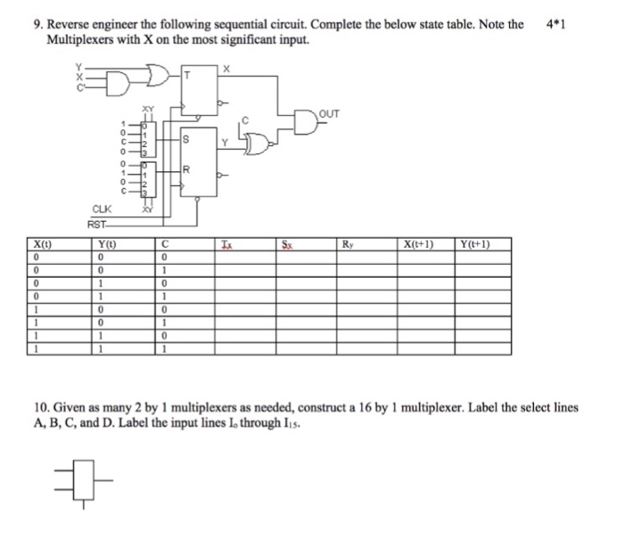
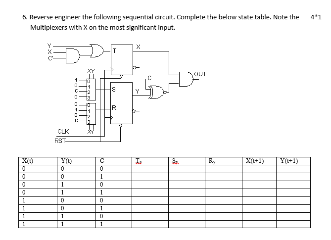
Solved 9. Reverse engineer the following sequential circuit. | Chegg.com
jk-flip-flop-to-d-flip-flop | Sequential Logic Circuits || Electronics ...
Mechatronics Engineering: Digital Electronics Lecture Notes
Solved The multiplexer logic template, shown below, is | Chegg.com
Low Cost Design of Sequential Reversible Counters
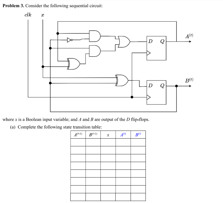
Solved Problem 3. Consider the following sequential circuit: | Chegg.com
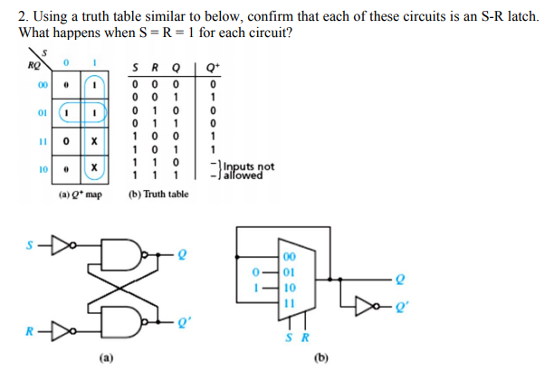
Solved 2. Using a truth table similar to below, confirm that | Chegg.com
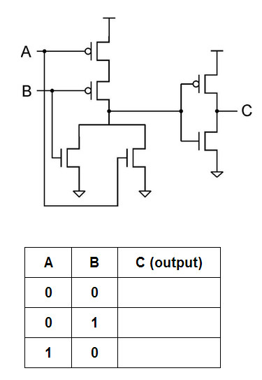
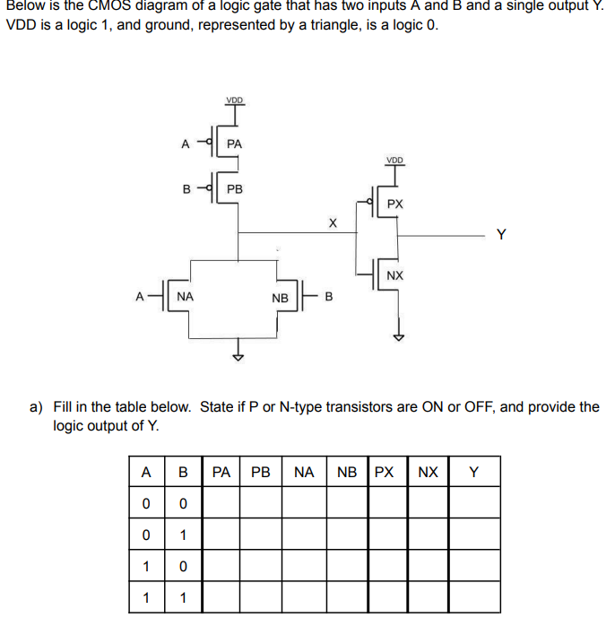
Solved Below is the CMOS diagram of a logic gate that has | Chegg.com
Solved 6. Reverse engineer the following sequential circuit. | Chegg.com
Truth-Table-of-Encoder
Truth-Table-for-Encoder
3:8-Decoder-Truth-Table
Encoder-Truth-Table-and-Circuit-Diagram
8-to-3-Priority-Encoder-Truth-Table
4X2-Encoder-Truth-Table
Truth-Table-of-2-to-4-Decoder
Encoder-Logic
4-Bit-Priority-Encoder-Truth-Table
1-to-2-Decoder-Truth-Table
Decimal-to-Bcd-Encoder-Truth-Table
16-to-4-Encoder-Truth-Table
2-To-4-Line-Decoder
Encoder-vs-Decoder
2X4-Decoder-Truth-Table
4-Input-Truth-Table