Please enter url.
Login
Logout
Please enter url.
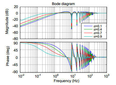
Bode plots of the current-controlled inverter. | Download Scientific ...
researchgate.net
source
Comments
Bode plots of the current-controlled inverter. | Download Scientific ...
Measured and modelled impedance of an open IGBT for the frequency band ...
Comparison of Bode diagram between SOGI and SSOGI. | Download ...
Typical measured impedance spectra (magnitude and phase) for monopolar ...
Bode diagram of DC-link voltage loop. | Download Scientific Diagram
Bode diagrams including controller of (a) inner loop with varying ...
Step responses of uncompensated (dashed line) and compensated systems ...
Simulated loop bandwidth for different ‘Mixer+LPFA’ boards. | Download ...
Bode plots of plant and loop transfer functions | Download Scientific ...
Parasitic capacitance comparisons for SiC-MOSFET Q1. | Download ...
Parker Servo Valve approximated dynamics. | Download Scientific Diagram
Frequency response functions. (a) Gearbox torque fluctuation to ...
OMCT of sway and roll motion | Download Scientific Diagram
Equivalent circuit of an inductor. | Download Scientific Diagram
Figure A14. Scaling function analysis of the time series shown in Fig ...
Path loss vs. distance between two coils for two different operating ...
Bode plot of uncompensated and compensated (a) current control loop and ...
Electricity | Free Full-Text | Highly Accurate Digital Current ...
Bode plots of the quasi-sin (upper plots) and quasi-cos (lower plots ...
Frequency response of the open loop LDO regulator. | Download ...
A review on control methodologies of disturbance rejections in optical ...
(a) Allan deviation plots of force sensor data and (b) Allan deviation ...
Frequency response of open-loop op-amp gain magnitude (and phase) with ...
a Phase noise break down of PLL at 125 GHz frequency with -100, -89 and ...
Figure 1 from Plant model analysis based on closed-loop step response ...
Harmonic impedance amplitude (upper trace) and phase (lower trace) of a ...
Bode diagram of the HPF/LPF (10) ωh=500,ω⋆=1 | Download Scientific Diagram
Transfer Function of a Notch Filter | Download Scientific Diagram
Bode diagram of I ESS /I GSC with a lead–lag compensator | Download ...
Efficiency of bandwidth use (above) and packet loss ratio (below) as ...
Time domain response and Bode diagram of control closed-loop with ...
Baseband transfer function around the nominal driving frequency of ...
Sensors | Free Full-Text | Measurement of Shear Strain Field in a Soft ...
Open-loop system transfer functions magnitudes | Download Scientific ...
The (a) resonance filter and (b) PR controller’s magnitude and phase ...
3-Phase-Inverter
Sine-Wave-Power-Inverter
Inverter-Electronics
Solar-Inverter-Charger
Home-Solar-Power-Inverter
Power-Electronics-Inverters
Current-Source-Inverter
DC-to-AC-Inverter
Power-Inverters-12V
Voltage-Source-Inverter
Inverter-Wiring-Diagram
3-Phase-Inverter-Circuit-Diagram
Inverter-Circuit-Design
Control-Inverter
300W-Inverter
Hybrid-Inverter