Please enter url.
Login
Logout
Please enter url.
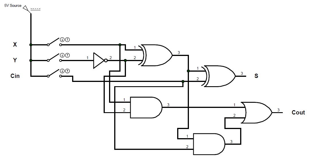
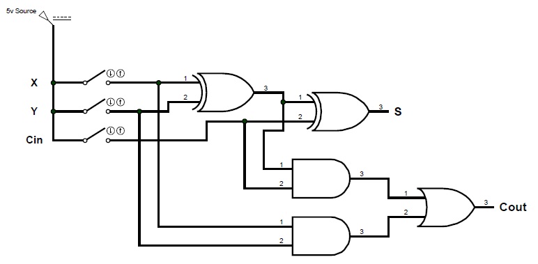
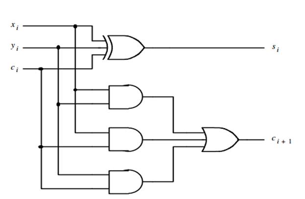
Full Adder Equation
animalia-life.club
source
Comments
ECE Logic Circuit: FULL SUBTRACTOR
ECE Logic Circuit
Eight-Channel Multiplexer to assure the Function of a Gate Network
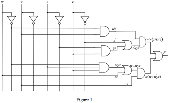
Solved: Draw logic diagrams of the circuits that implement the ...
The third proposed MV of QMR configuration | Download Scientific Diagram
(Get Answer) - Determine the worst case propagation delay for your full ...
Full Subtractor | Computer Organization And Architecture Tutorials ...
Solved For the following circuit, justify whether it | Chegg.com
Figure 1 from Design Simulation of Two Bit Multiplier using 90 nm CMOS ...
How does a CPU calculate on a hardware level? - Super User
digital logic - Building a XOR gate on 3 inputs using only 5 AND/OR/NOT ...
4-Bit MCLA adder architecture using NAND, FA and PGA blocks [5,6 ...
Enabling
(PDF) An experiment on evolutionary design of combinational logic ...
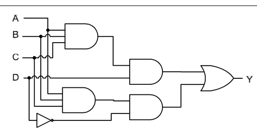
Solved Give the Boolean expression for the circuit On your | Chegg.com
Proposed third encoder circuit for third PPAG | Download Scientific Diagram
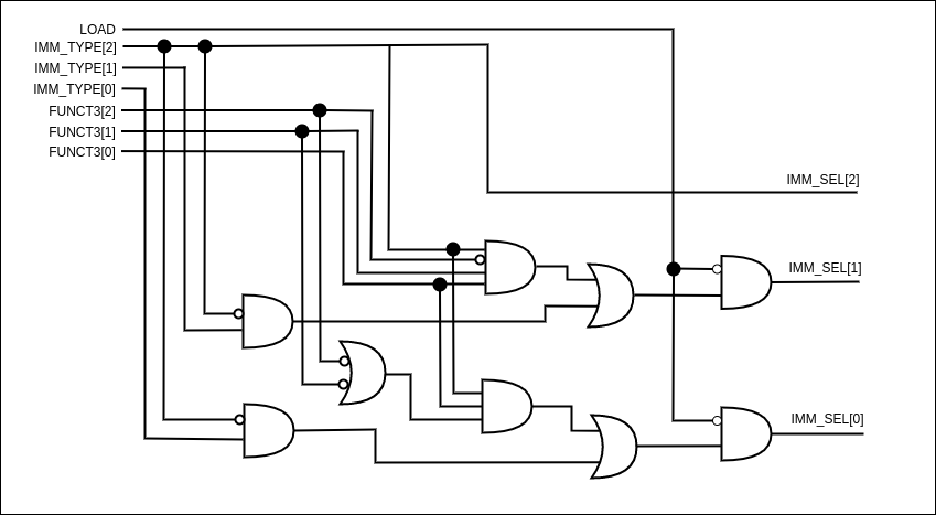
Control Unit Design - RV32IM Pipeline Implementation
CHAPTER TWO: BOOLEAN ALGEBRA (Part 3)
Table 1 from An effective 3-bit Flash Analog to Digital Converter using ...
SystemVerilog Generate the netlist file of your 8-bit | Chegg.com
Both S1 and R1 contain the same minterm, L · Q0
Odd-parity - CircuitLab
Chapter 3 - Combinational Logic Design
CSC270 Lab #4
Hash‐One: a lightweight cryptographic hash function - Megha Mukundan ...
Transient and Permanent Fault Injection in VHDL Description of Digital ...
Solved A) Construct the truth table of the above logic | Chegg.com
2 Bit Calculator - EasyEDA open source hardware lab
4-bit Multiplier
Chapter 8 Solutions | Fundamentals Of Digital Logic With Verilog Design ...
Gate level implementation of approximate full adder (AFA) [10 ...
digital logic - 4-bit decrementer using four Half Adders - Electrical ...
The second proposed MV of 5-MR | Download Scientific Diagram
multiplexer - How do I construct a 4x1 MUX using only 2 input NAND ...
3-Bit-Full-Adder
8-Bit-Full-Adder-Circuit
1-Bit-Full-Adder-Layout
Two-Bit-Full-Adder
Full-Adder-Pin-Diagram
One-Bit-Full-Adder
Single-Bit-Full-Adder
Full-Adder-Schematic/Diagram
CMOS-Full-Adder-Circuit-Diagram
12-Bit-Full-Adder
4-Bit-Full-Adder-Diagram
Full-Adder-Block-Diagram
Zuse-1-1-Bit-Full-Adder
1-Bit-Hybrid-Full-Adder
4-Bit-Full-Adder-Subtractor
Full-1-Bit-Adder-Stick-Digram