Please enter url.
Login
Logout
Please enter url.
Bode Diagram Phase Plot Rc Circuit
circuitlistgoldschmidt.z19.web.core.windows.net
source
Comments
Low Pass Filter - Passive RC Filter Tutorial | Filters, Engineering ...
Passive High Pass Filter - Passive RC Filter Tutorial
Second Order Low Pass Response Curve Filters, Electronics, Low ...
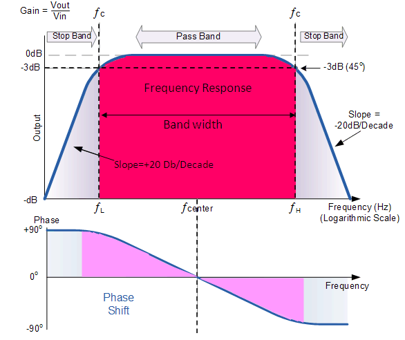
Passive Band Pass Filter - Passive RC Filter Tutorial
voltage - Are cutoff frequencies of bandpass and bandstop filters equal ...
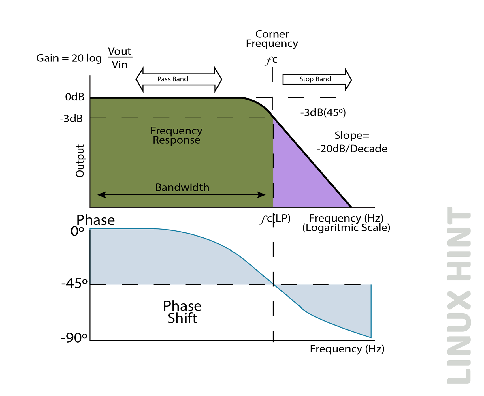
What is Passive Low Pass Filter – Passive RC Filter – Linux Consultant
EEE108 Diagram | Quizlet
Passive Band Pass RC Filter | Circuit design, Filters, Fibre optics
Low Pass Filter Tutorial - Passive RC Filter - Components Monofindia
Active Band Pass Filter Circuit Diagram and Its Frequency Response ...
How to Build a Passive RC Low Pass Filter – Linux Consultant
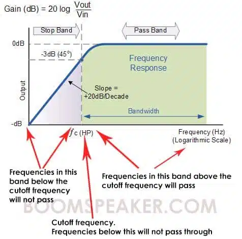
High-Pass Filter Settings For Vocals: How to Do It Right - BoomSpeaker
Design of Microstrip Dual Behavior Resonator Filters: A Practical Guide ...
Bode plot of 10th order bessel low pass filter circuit | Download ...
Synthesis Basics
Control of the RFCWs parameters. a Plot in the time-optical frequency ...
Bode plot of the used high-pass filter. | Download Scientific Diagram
capacitor - How is the frequency for a CR Filter acting as a ...
filter - Is there a standard definition of LPF stop band starting point ...
(a) Normalized frequency response for different modulation indices at L ...
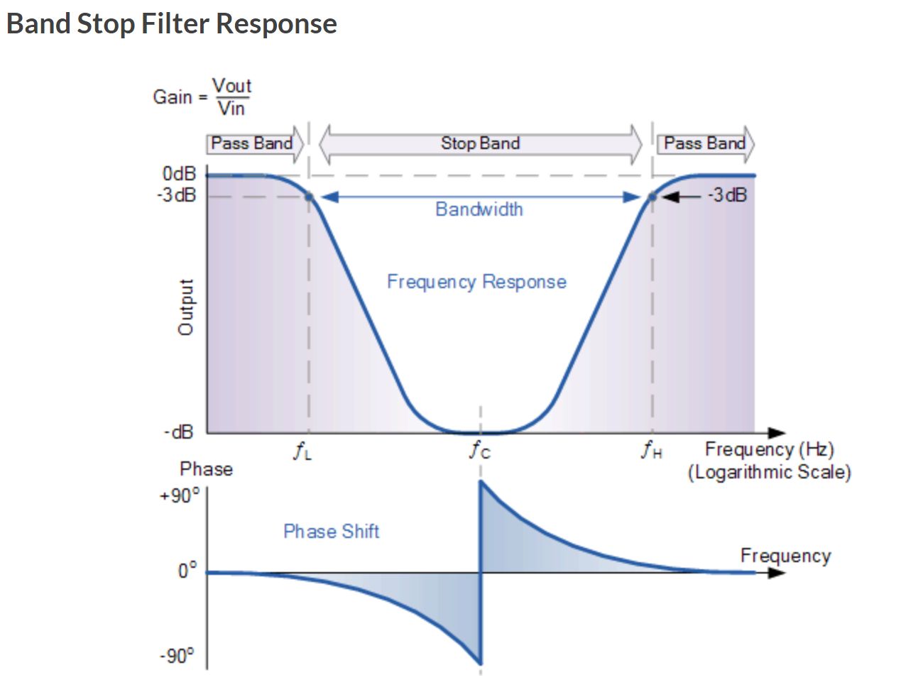
Band Stop Filter and Notch Filter Design Tutorial
Glossary
News - Features of Band Stop Filter
Figure 1 from Design methodology of a non-invasive sensor to measure ...
Microwaves101 | Klopfenstein Taper
Computers | Free Full-Text | Statistical-Hypothesis-Aided Tests for ...
Bessel filter response. | Download Scientific Diagram
How to calculate the cutoff frequency for transfer functions from ...
Figure 1 from Frequency Response by AC Analysis on One-Pole Low Pass ...
[SOLVED] What is the order of the filter, when the gain decreases at ...
Band-pass filter response | Download Scientific Diagram
Speaker Cab Modelling Part II: Impulse Response Modelling, Theory and ...
(PDF) 50 GHz optical frequncy Comb generation based on an ...
(a)The time domain analysis of the long-time jitter and cycle-to-cycle ...
Spectrum of quantization noise without (a) and with (b) DRE, and CSPR ...
High-Pass-Filter-Plot
Band-Pass-Filter-Bode-Plot
Low-Pass-Filter-Cutoff-Frequency
RLC-Low-Pass-Filter
Digital-Low-Pass-Filter
Frequency-Response-of-Low-Pass-Filter
Low-Pass-Filter-Graph
Low-Pass-Filter-Equation
Low-Pass-Filter-Curve
Analog-Low-Pass-Filter
Low-Pass-Filter-Formula
Low-Pass-Filter-Transfer-Function
Notch-Filter-Bode-Plot
First-Order-Bode-Plot
3D-Low-Pass-Filter-Graph
MOS-FET-as-a-Low-Filter-Pass


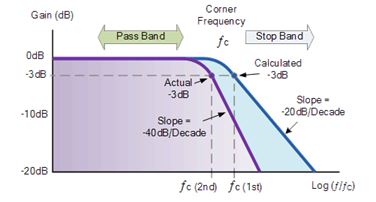


![[SOLVED] What is the order of the filter, when the gain decreases at ...](https://storage.googleapis.com/tb-img/production/20/09/F1_Pinnu_22.9.20_Pallavi_D5.png)