Please enter url.
Login
Logout
Please enter url.
Loading ...
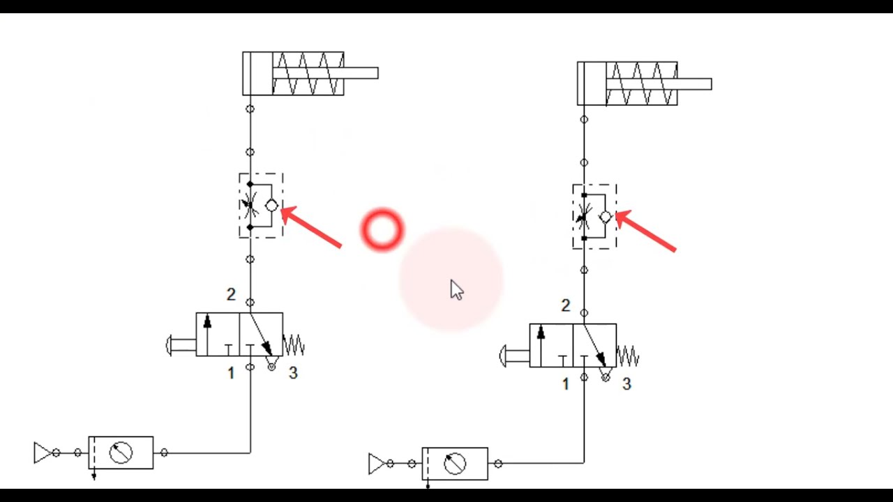
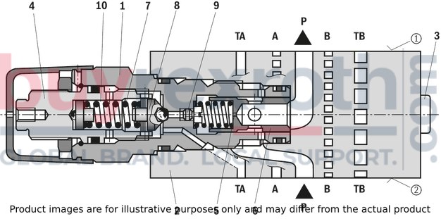
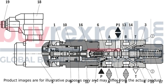
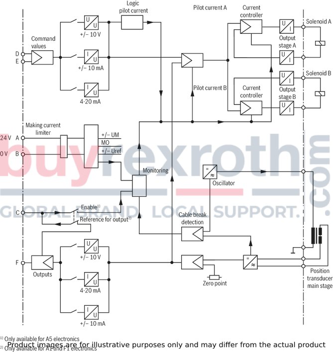
Pilot Valve Diagram
Air Pilot Valves Schematics
Pilot Valve Diagram
Pilot Valve Diagram
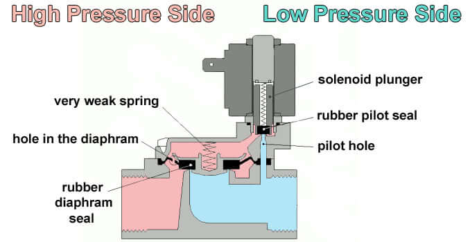
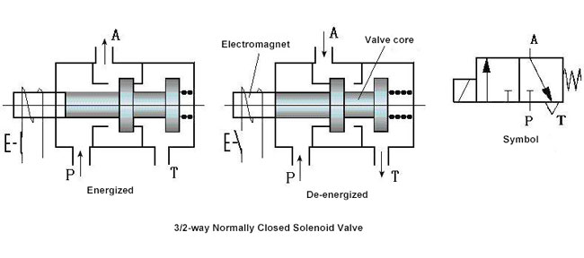
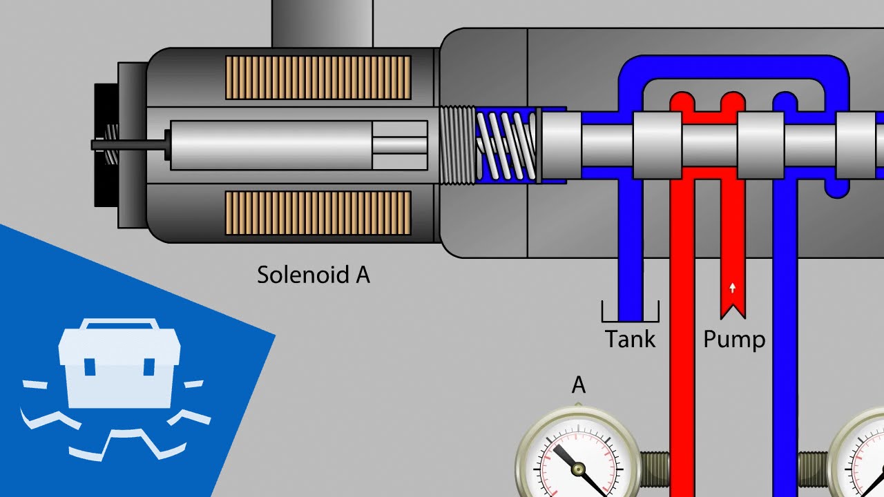
solenoid valve working principle animation How a solenoid valve works ...
Hydraulic Check Valve Schematic
Hydraulic Relief Valve Schematic
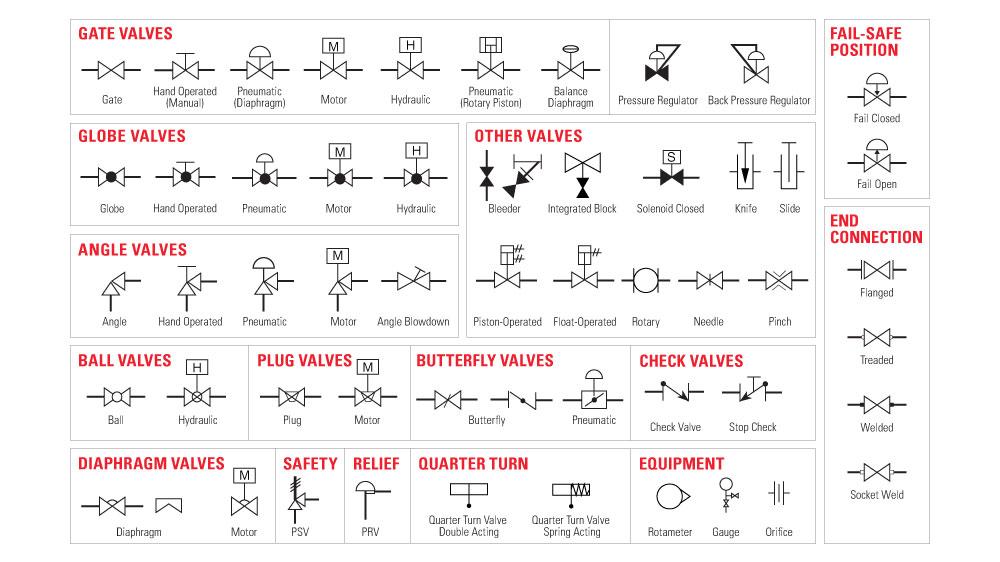
check valve symbols on drawings Symbols engineering process diagram ...
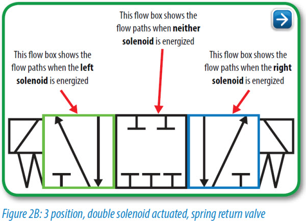
Directional Control Valve Diagram
3 way solenoid valve working principle What is a 4-way solenoid valve?
(E35B) - MINI CRAWLER EXCAVATOR - TIER 4B - ASN PX17-40001 (NETN66000 ...
solenoid valve actuator symbol Solenoid valve symbols
Solenoid Valve Circuit Diagram
Pilot Operated Relief Valve - RPL Series | Parker NA
1/4 PILOT VALVE | JBM Technologies
Hydraulic Solenoid Valve Diagram
270-5692 VALVE GP-MANUAL S/N JKN1-UP PART OF 482-9906 KIT-VALVE, 296 ...
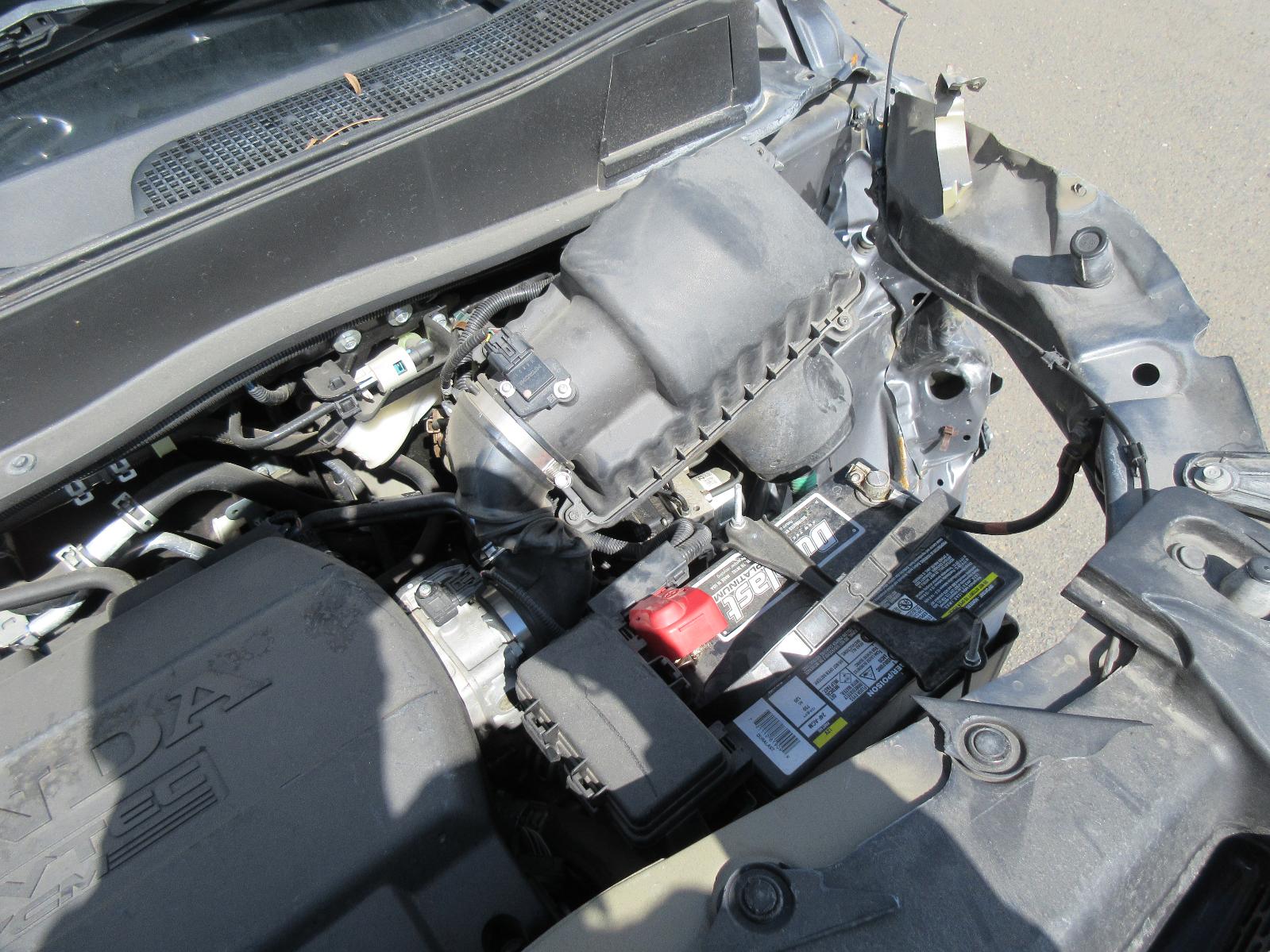
Honda Pilot Engine Diagram
3/2 PILOT/PILOT VALVE 1/4" | The Fluid Power Catalogue
5/2 Way Double Pilot Valve, Valve size: up to 1.0 inch at Rs 1200 in ...
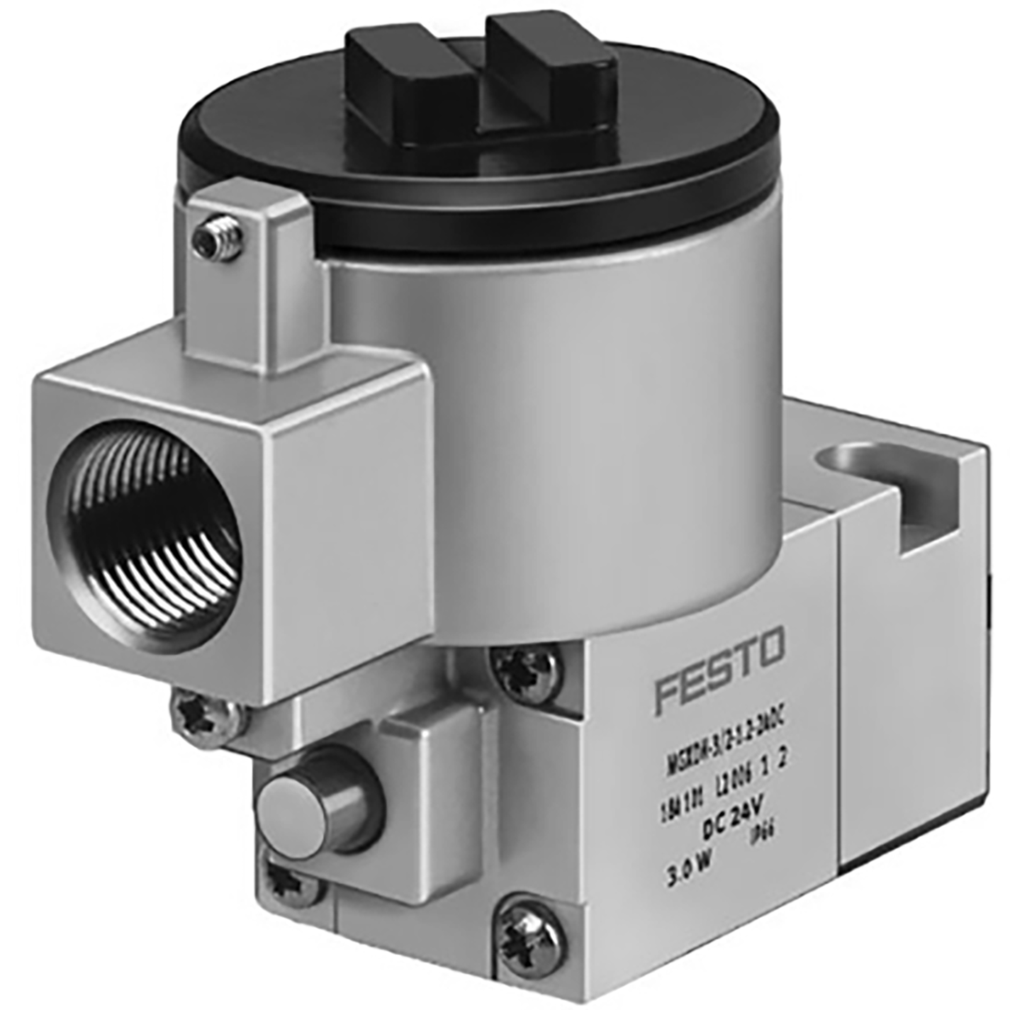
MGXDH-3/2-1.2-24DC-EX PILOT VALVE | Pneumatics Direct
Honeywell Flanged Linear Valves Installation Guide
171-0140 VALVE GP-MAIN CONTROL S/N ANF753-UP PART OF 215-4359 HYDRAULIC ...
3G7410 PILOT VALVE GROUP-TYPE 1 PART OF 6G1330, 8W0228 ACCUMULATOR ...
270-5692 VALVE GP-MANUAL S/N JKN1-UP PART OF 482-9906 KIT-VALVE, 296 ...
SOLENOID PILOT VALVES - METRIC 01VS
solenoid valve symbols explained Solenoid valves descriptive ...
[DIAGRAM] 3 Way Switch Wiring Diagram Pilot - MYDIAGRAM.ONLINE
5/2 Way Double Pilot Valve, Valve size: up to 1.0 inch at Rs 1200 in ...
803085699 Wheel Loader Spare Parts Pilot Valve - China Pilot Valve and ...
565-6686 KIT-ENGINE GASKET S/N 8YF1-UP SINGLE CYLINDER HEAD FIELD ...
2007 Honda Pilot Engine Diagram
Anderson Greenwood Relief Valves Manual
Robertshaw Gas Valve Wiring Diagram
Gas Valve Wiring Diagram
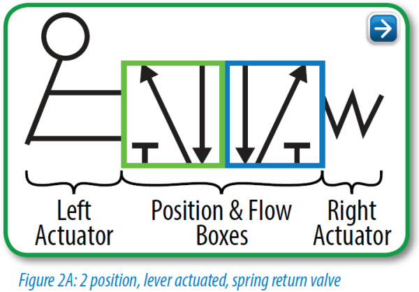
4 Way 3 Position Valve Schematic
Williams Wall Furnace Wiring Diagram
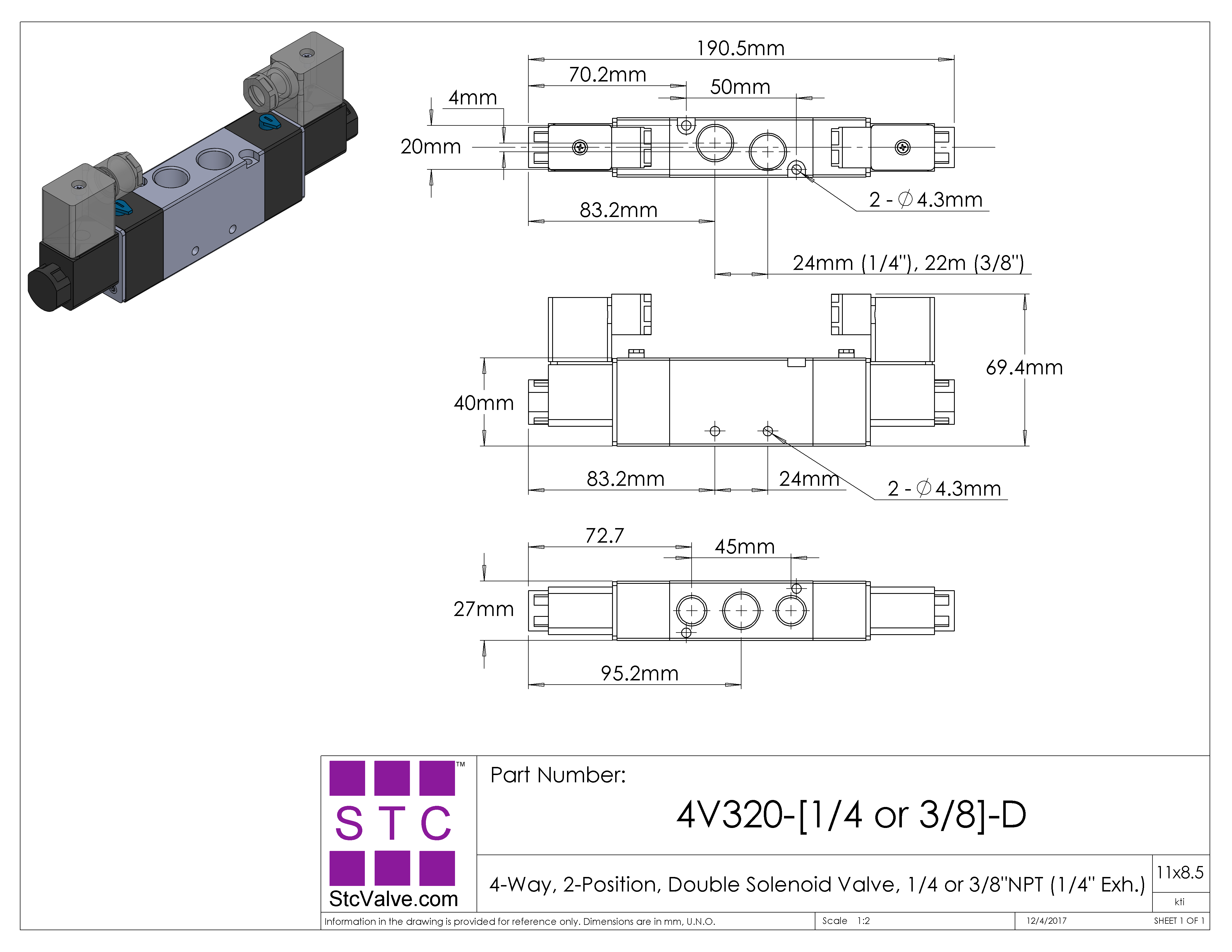
4 Way 2 Position Valve Schematic
4 Way 2 Position Valve Schematic
4 Way 2 Position Valve Schematic
2011 Honda Pilot Cylinder 2 Location
4 Way Pneumatic Valve Schematic
Anderson Greenwood Relief Valves Manual
Pneumatic Circuit Diagram Symbols
Williams Wall Furnace Wiring Diagram
Air Valve Solenoid Schematic
Pneumatic Circuit Diagram Symbols
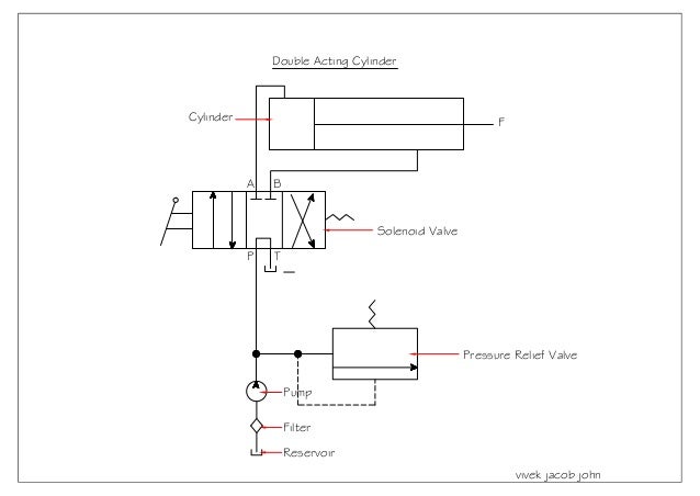
Pneumatic Circuit Diagram For Double Acting Cylinder
What Is Manual Override In Solenoid Valve
Pneumatic Circuit Diagram For Double Acting Cylinder
Gibson Furnace Troubleshooting Gas Valve
Ev100 Wiring Diagram
VALVE, HAND CONTROL, SERVO - AGRICULTURAL JCB 3CX-4T PC (REGULAR ...
Schematic Electric Fireplace Heater Wiring Diagram
4r70w Transmission Diagram
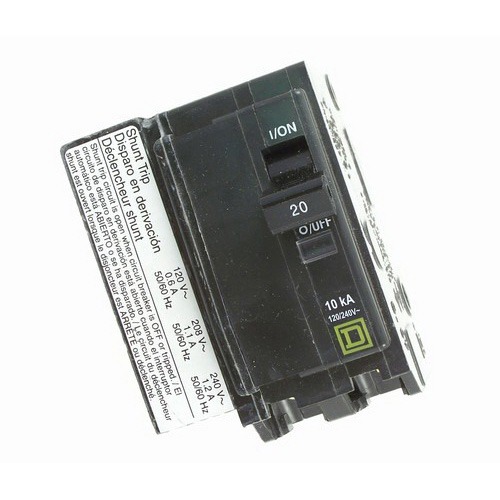
Wiring Diagram For Shunt Trip Circuit Breaker
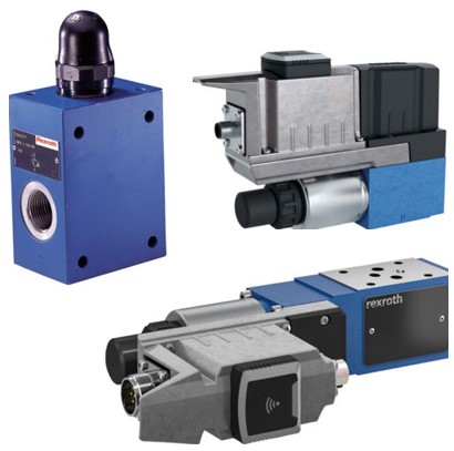
R900597233, Bosch Rexroth, Pressure reduction valve | ELTRA TRADE
Asco Solenoid Valve Installation Manual
Pneumatic Circuit Diagram For Single Acting Cylinder
2016 Honda Pilot Transmission Dipstick Location
2016 Honda Pilot Transmission Dipstick Location
Honda Pilot 2005 Engine
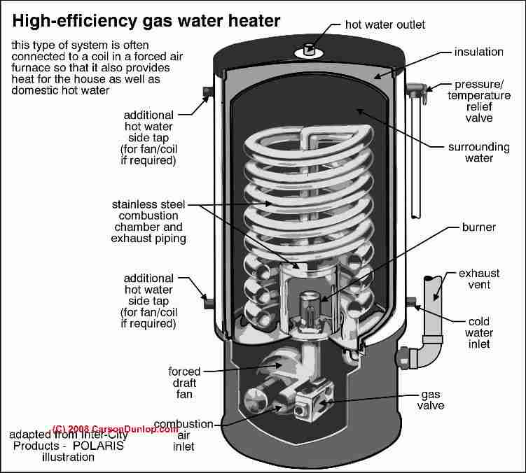
Gas Water Heater Schematic
Double Acting Hydraulic Cylinder Schematic
2001 Honda Accord Vtec Engine Diagram
2011 Honda Pilot Cylinder 2 Location
2003 Honda Odyssey Parts Diagram
2005 Honda Pilot Engine Splash Shield
Gravity Furnace Wiring
2011 Honda Pilot Cylinder 2 Location
2015 Honda Odyssey Valve Adjustment
2008 Honda Accord Valve Cover Gasket
Unit Injector System Diagram
Reading Pneumatic Schematic Symbols
Kawasaki FS541V-DS01 4 Stroke Engine FS541V Parts Diagram for CARBURETOR
2011 Honda Pilot Cylinder 2 Location
2007 Honda Odyssey 3.5 Firing Order
2003 Mazda Protege 5 Engine Diagram
Duo Therm Furnace Repair
2008 Honda Accord Valve Cover Gasket
R900452728 - PRESSURE RED.VALVE INTERMEDIATE PLATE ZDR10VP7-3X/200YM ...
Reading Pneumatic Schematic Symbols
R900702633 - 4WRKE10W6-50L-3X/6EG24ETK31/A5D3M - BuyRexroth
2011 Honda Pilot Tail Light Bulb
2004 Honda Odyssey Egr Valve
2015 Honda Pilot Brake Light Bulb Replacement
Mohamed Kamal on LinkedIn: #deepwaterdrilling #subseabop
R900247998 - LOGIC CARTRIDGE VALVE LC40A10D7X/V - BuyRexroth
R901208855 - PRESSURE REDUCING VALVE DRE6-1X/210MG24N9K4M - BuyRexroth
2015 Honda Odyssey Valve Adjustment
Richmond Water Heater Manual
R901050135 - 4WRKE16E3-200L-3X/6EG24K31/F1D3M - BuyRexroth
Dodge Ram 1500 Fuse Box Diagram
Empire Gas Heater Parts
2015 Honda Pilot Brake Light Bulb Replacement
Kawasaki FS541V-DS01 4 Stroke Engine FS541V Parts Diagram for CARBURETOR
Remove Valve Cover 2012 Malibu 2.4
Honda V6 Valve Cover Gasket Replacement
Autopilot Salt Generator Troubleshooting
Mikuni Carburetor Manual
Kawasaki FS541V-DS01 4 Stroke Engine FS541V Parts Diagram for CARBURETOR
2015 Honda Odyssey Valve Adjustment
Dodge Ram 1500 Purge Valve Location
2011 Toyota Camry 2.5 Pcv Valve Location
Kawasaki FS541V-DS01 4 Stroke Engine FS541V Parts Diagram for CARBURETOR
2011 Toyota Camry 2.5 Pcv Valve Location
Honda V6 Valve Cover Gasket Replacement
Genuine Empire Heater Parts
2015 Honda Odyssey Valve Adjustment
Honda V6 Valve Cover Gasket Replacement
2015 Honda Odyssey Valve Adjustment
Double Acting Cylinder Schematic
Canister Purge Valve Ford Escape
Raypak Rp2100 Pool Heater Parts
Kawasaki FS541V-DS01 4 Stroke Engine FS541V Parts Diagram for CARBURETOR
2009 Hyundai Tucson Wiring Harness
Hydraulic Pressure Transducer Schematic Symbol
Replacement Parts - 3900 Control Valve Body. Watts HCTA-300, HCP-300 ...
2012 Chevy Cruze Pcv Valve Recall
Replacement Parts - 3900 Control Valve Body. Watts HCTA-300, HCP-300 ...
2007 Honda Odyssey Vtec Solenoid
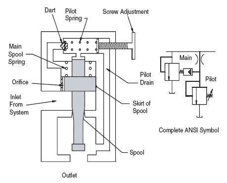
Hydraulic Pilot Valve
Pilot Valve Schematic
Air Pilot Valve
Air Pilot Valve Diagram
Pilot Solenoid Valve
Directional Control Valve Schematic
Pneumatic Valve Diagram
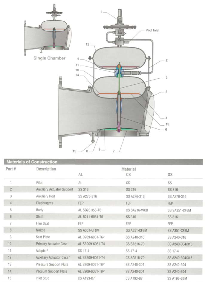
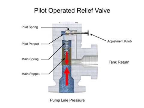
Pilot Operated Pressure Relief Valve Diagram
Air Suspension Dump Valve Diagram
Hydraulic Check Valve Diagram
Solenoid Valve Design
Honda Pilot Engine Diagram
Pressure Reducing Valve Schematic
Gate Valve Diagram
Metering Valve Diagram
Pilot Operated Safety Valve
Solenoid Valve Schematic Symbol
Pressure Relief Valve Installation
Standing Pilot Gas Valve Diagram
Actuator Diagram
5/2 Solenoid Valve
90554615 Pilot Valve Diagram
Poppet Valve Diagram
Angle Valve Diagram
Pressure Relief Valve Drawing
Haldex 90554615 Pilot Valve Diagram
Millivolt Gas Valve Wiring Diagram
Solenoid Valve Flow Diagram


![[DIAGRAM] 3 Way Switch Wiring Diagram Pilot - MYDIAGRAM.ONLINE](https://www.electricaltechnology.org/wp-content/uploads/2020/06/Wiring-A-Neon-Pilot-Light-Switch-with-Light-Bulb.png)