Please enter url.
Login
Logout
Please enter url.
Loading ...
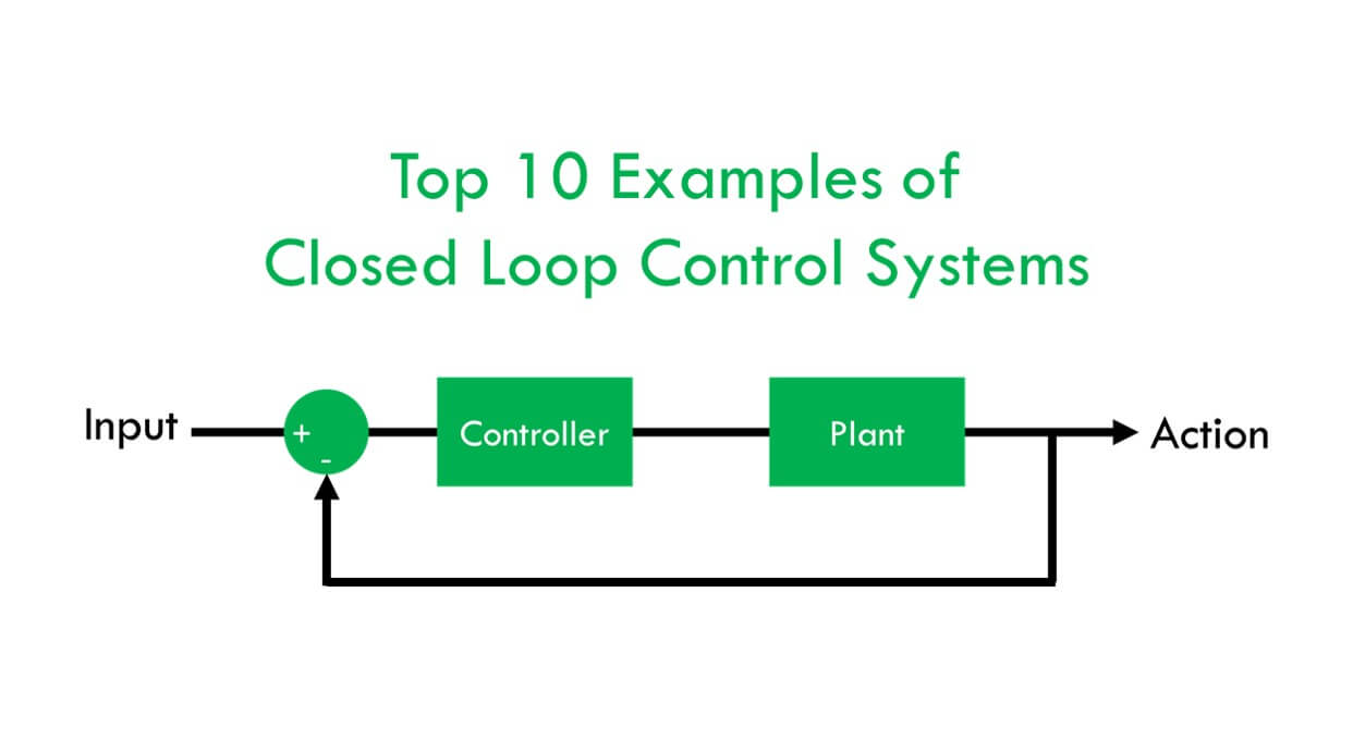
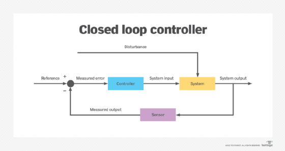
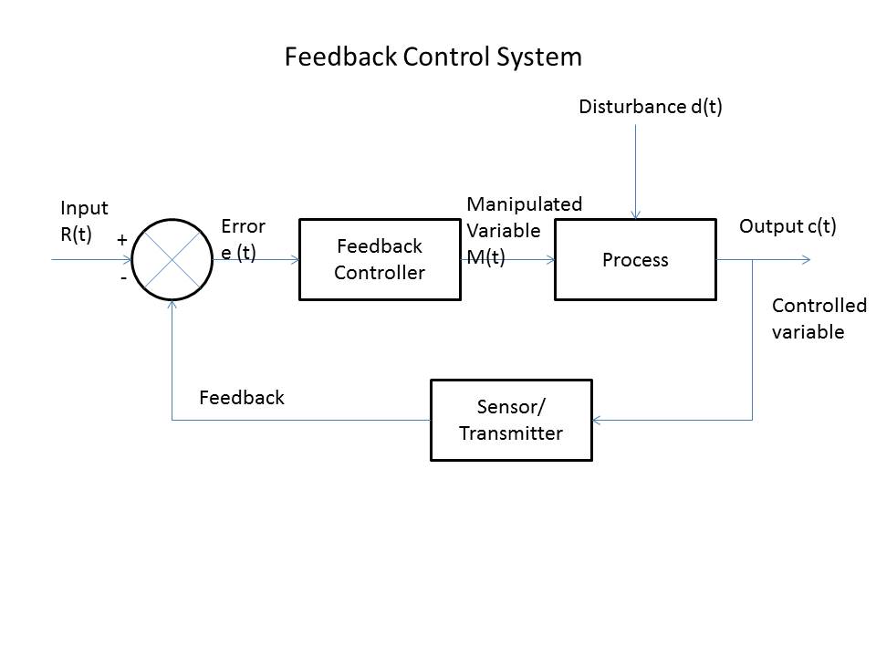
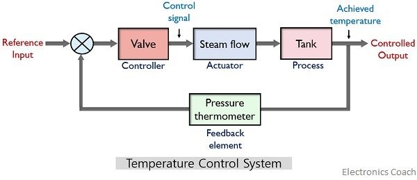
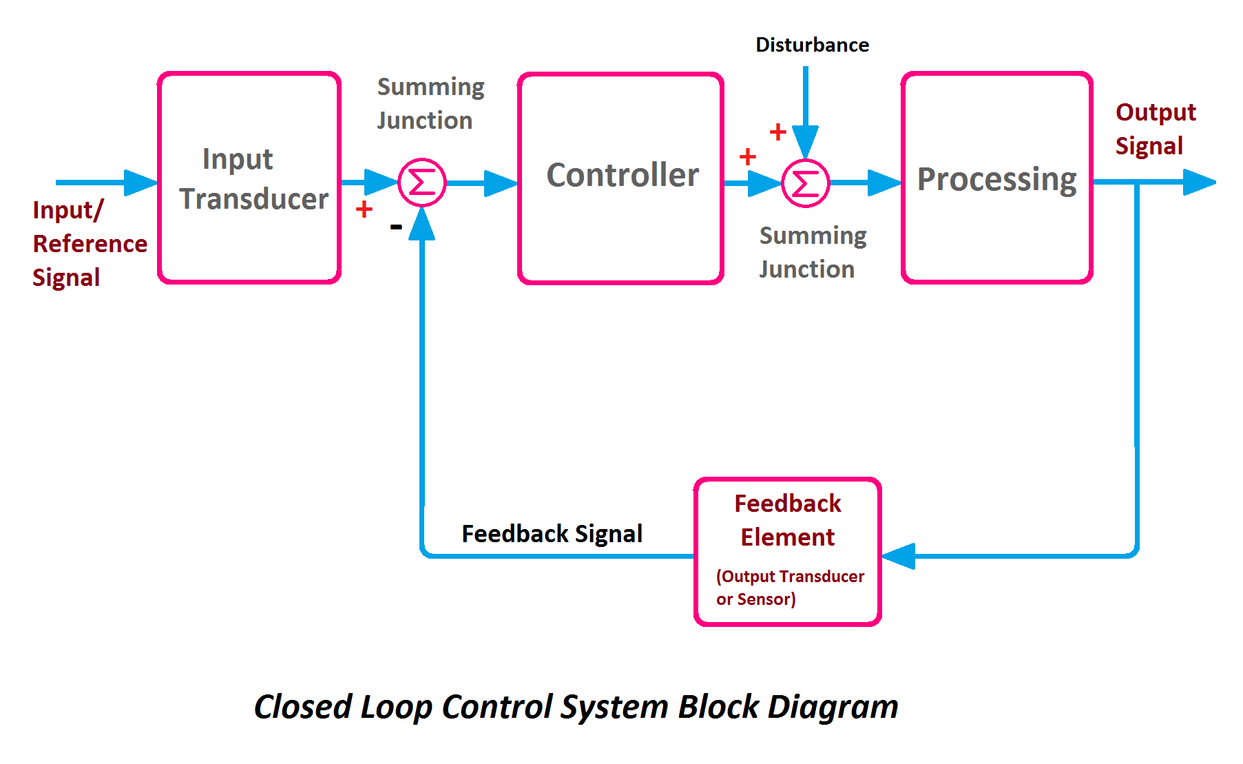
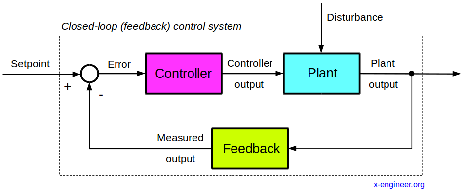
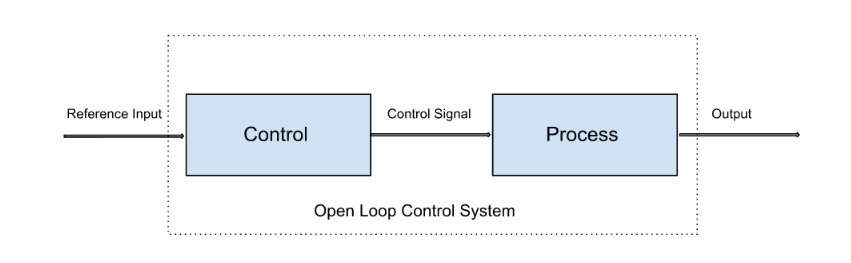
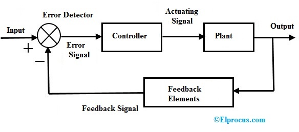
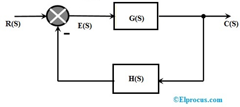
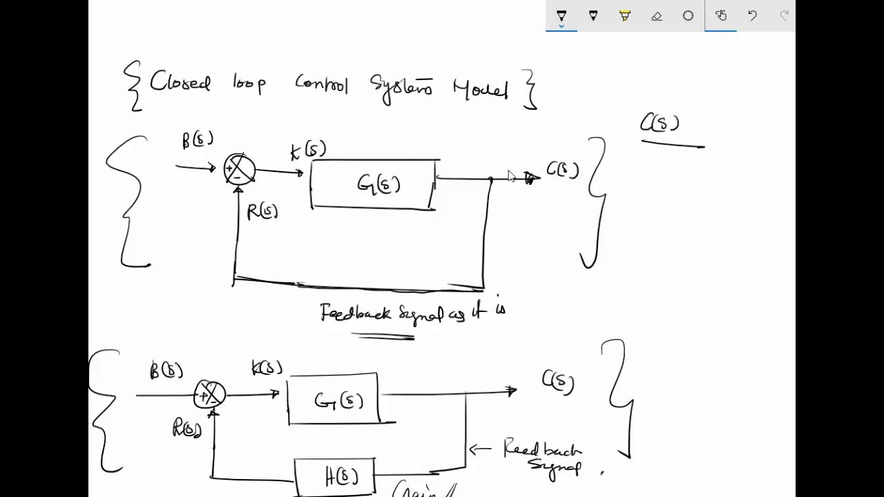
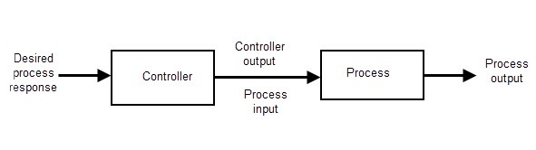
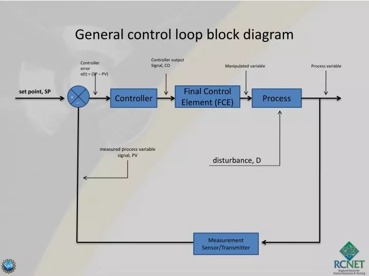
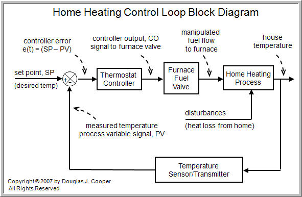
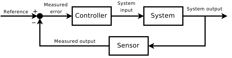
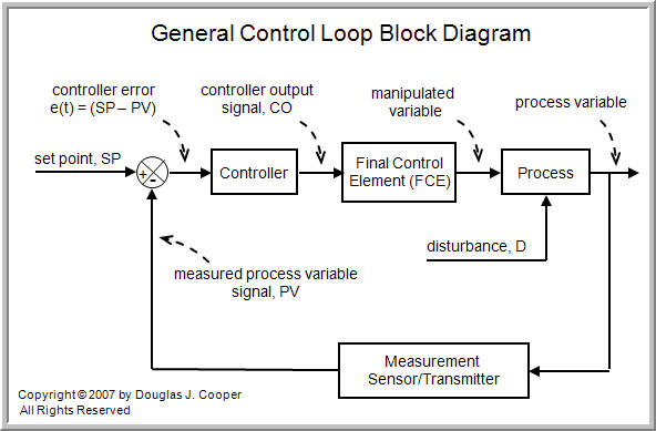
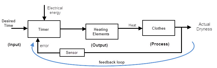
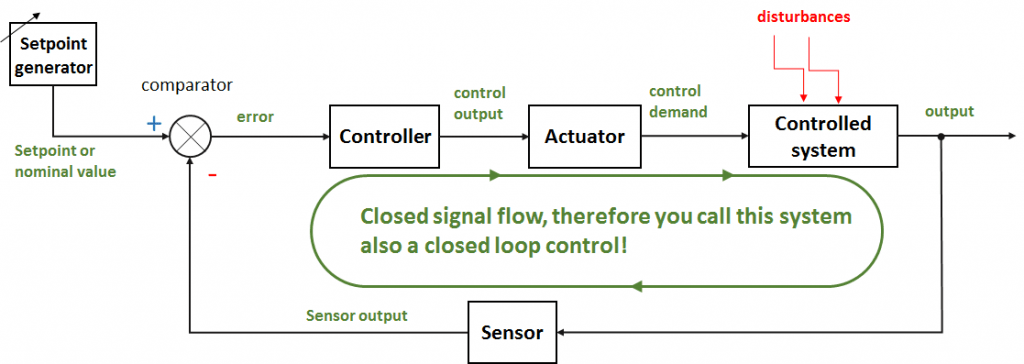
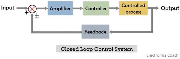
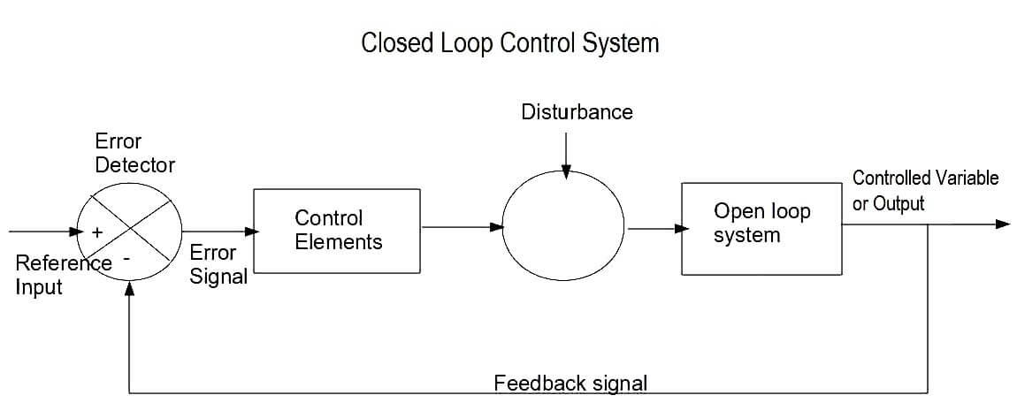
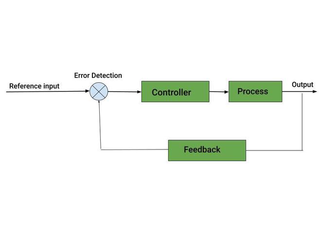
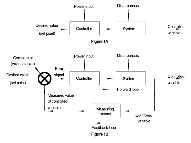
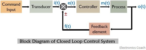
Block Diagram Of Closed Loop Control System
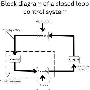
Basic Block Diagram Closed Loop Control System System Diagra
Closed Loop Control System Block Diagram
Block Diagram Closed Loop Control System Loop Feedback Input
Control: Open vs. Closed Loop | Block diagram comparing open… | Flickr
10 Examples Of Closed Loop Control System With Block Diagram
Process Control Block Diagram Examples Block Diagrams For Pr
[DIAGRAM] 3 Way Valve Block Diagram - WIRINGSCHEMA.COM
[DIAGRAM] Osi Reference Model Diagram - WIRINGSCHEMA.COM
Air Conditioner Closed Loop Control System at Eleanor Rubino blog
Process Control Block Diagram Examples Block Diagrams For Pr
Closed Loop Control System Block Diagram
Design, Applications, and Pros and Cons of Open-Loop and Closed-Loop ...
Open And Closed Loop Fuel System
Closed Loop Control System Examples
Basic Process Control Loop Block Diagram How A Process Contr
Difference between open loop and closed loop control system
Advantages And Disadvantages Of Block Diagrams In Control Sy
Explain Closed Loop Control System
10 Examples Of Closed Loop Control System With Block Diagram
Difference Between Open Loop And Closed Loop Control System – Themelower
Closed Loop Fueling Not Achieved Bank 1
Process controller
Load transfer
Open And Closed Loop Control
Control Loop Diagram
Difference between open loop and closed loop control system
Industrial Control Systems - Instrumentation Tools
Closed-Loop Control Systems at Johanna Jones blog
Loop Diagram In Instrumentation
Closed Loop And Open Loop Control System
Closed Loop Hydraulic System Schematic
Advantages And Disadvantages Of Block Diagrams In Control Sy
Top 10 Open Loop Control System Examples
10 Examples Of Closed Loop Control System With Block Diagram
Closed Loop And Open Loop Control System
Negative Feedback Circuit Block Diagram Examples
Loop In Wiring Diagram
The image shows a block diagram of a | StudyX
Solving Block Diagram Control Systems Control Systems
Electric Drive System Block Diagram
Block Diagram Of Communication System And Its Explanation Dr
Closed Loop Energy System
Control Systems 101: Understanding Open and Closed Loop Systems - Studocu
How To Solve A Pid Control Diagram Piping & Instrumentation
[Solved]: A. When we drive, maintaining the speed is a typic
Design and Analysis of an Underactuated Lateral Coupling Control System ...
Control Systems 101: Understanding Open and Closed Loop Systems - Studocu
The block diagram of a control system is | StudyX
Uml Sequence Diagram Loop
diagram
Given the block diagram below:In this exercise you | Chegg.com
Design a closed-loop control system for a DC drive. | Chegg.com
Find the transfer function of the following systems, using block diagram
Design and Analysis of an Underactuated Lateral Coupling Control System ...
Sequence Diagram Loop
High stability and precision sliding mode robust control of two-axis ...
Q-1 Figue below shows a block-diagram repesentation | Chegg.com
Step Response (16% Overshoot)Given the block diagram | Chegg.com
S32E2 Propulsion Domain Controller (PDC) | NXP Semiconductors
Basic Structure Of Plc With Block Diagram Controls Create Cu
The Key Elements of the Closed-Loop Control System - YouTube
6.1 Draw and label the block diagram of a | StudyX
GATE IN 2025 | Question: 18 / GO Instrumentation
Control Method of Inverters | Technical Reference | Oriental Motor
c) Reduce the following block diagram and | StudyX
Basic Structure Of Plc With Block Diagram Controls Create Cu
a) Formulate the transfer function of the | StudyX
Robotics - Allegro MicroSystems | Mouser
5. Find the transfer function of the system | StudyX
How To Use Function Block Diagram In Ccw Figure 1 From Block
Consider the system shown in block diagram | StudyX
Solved HW 6 1. Consider the feedback system in Figure | Chegg.com
Automatic Gate Control Circuit Diagram
Closed Loop Control Systems PowerPoint Presentation and Slides PPT ...
In A Block Diagram Each Box Represents A Component Solved 1.
Automatic Gate Control Circuit Diagram
Function Block Diagrams Programming Plc Block Diagram Functi
Schematic Block Diagram For Online Shopping Admin In Online
Analysis of Damping Characteristics in Wind Turbine‐Energy Storage ...
[Solved]: [25 points]Reduce the block diagram and determine
Process Control P&id Diagrams Process And Instrumentation Di
Design and Control of Dual‐Body Negative Pressure Ground‐Wall ...
Unified Control Architecture for Hybrid UAVs Using Incremental ...
Determine the transfer function of the | StudyX
Plot A Bode Diagram Of A Pid Controller Pid Controller Bode
Table 2 - Speed Control of PMSM Motor Using Fuzzy and PID
The Basics of a Control Loop in Simulink » Guy on Simulink - MATLAB ...
(3) For the block diagram shown in Fig. 3, use the | Chegg.com
Speed Control Of Three Phase Induction Motor
Analysis of Damping Characteristics in Wind Turbine‐Energy Storage ...
[Automation System] 01 PLC, System, Closed/Open-loop System
Table 2 - Speed Control of PMSM Motor Using Fuzzy and PID
Design Your Pole Placement Flow Diagram: The Ultimate Guide - Media Rpgsite
Pole Placement Flow Diagram - Media Rpgsite
Adding Diagrams And Schematics To A Website Clickable [diagr
Interpretacion De Diagramas Electricos De Control Pin En Cir
Analysis of Damping Characteristics in Wind Turbine‐Energy Storage ...
Comprehensive Guide to Solenoid Valves (Proportional Control Valves ...
Cooling Tower Piping Schematic Diagram
Oil & Gas Products | Products & Solutions | Oil & Gas | Hanwha Power ...
Design and Research of Avionics Flight Test Simulation and Verification ...
Interpretacion De Diagramas Electricos De Control Pin En Cir
Vibration Suppression Control for 2D TORA System With Parametric ...
A control system has an open-loop transfer function | Chegg.com
Interpretacion De Diagramas Electricos De Control Pin En Cir
GROUND DISTRIBUTION – Lincoln MKZ 2013 – SYSTEM WIRING DIAGRAMS ...
Refrigerant Monitor in Chiller Room - MEP Academy
Cad Block Jobs - March 2025 | CV-Library.co.uk
Consider the following feedback system.Design a PID | Chegg.com
Simple Toaster Circuit Diagram
Block Diagram of Open Loop Control System
Close Loop Control System Diagram
Closed Loop Heating System Diagram
Flow Control Loop Diagram
Process Control Loop Diagram
Block Diagram of Access Control System
Block Diagram of Feedback Control System
Closed Loop Water System Diagram
Closed Loop Torque Control Block Diagram
Control System Block Diagram Reduction
Block Diagram Flush Toilet Closed Loop Control System Diagram
For Loop Block Diagram
Automatic Brightness Control Closed System Block Diagram
System Functional Block Diagram
Closed Loop Syatem Block Diagram for Washing Machine
Close Loop Control Systems
Hiearchical Industrial Closed Loop Control Diagram
Control System Block Diagram Symbols
Transfer Function Block Diagram
Block Diagram of Closed Loop Force Control System
Block Diagram of Simple Control System
PID Control Loop Diagram
Closed Loop Block Diagrmn System
Closed Loop Control System Pic
Yokogawa Boiler Control System Block Diagram
Negative Feedback Block Diagram
Closed System Block Diagram Example
Closed Loop System AutoCAD Block
Speed Control System Block Diagram
Level Control Loop Diagram
Block Diagram Examples Closed Loop Control System
Closed Loop Temperature Control System Block Diagram
Closed Loop Block Diagram Attitude Control System
Control Valve Loop Diagram
Block Diagram of a Closed Loop Conveyor
Closed Loop Fuel Control System Block Diagram
Residential Closed Loop Water System Diagram
Closed Loop Block Diagram of Traffic Control System
Block Diagram of Starter System
Block Diagram Control System of a Telecom System
Closed Loop Motor Control Diagram
Object Tracking Closed Loop Block Diagram
Closed Loop Nock Control System Block Diagram
Round Block of a Closed Loop Control
Block Schematic Closed Loop RPC Servo Controller
Closed Loop Control System Mini Project Ideas without Arduino
Block Diagram of the Closed Loop Inverter
Controller Block Diagram
Pi Closed Loop Control Diagram
Closed Loop Control Digram